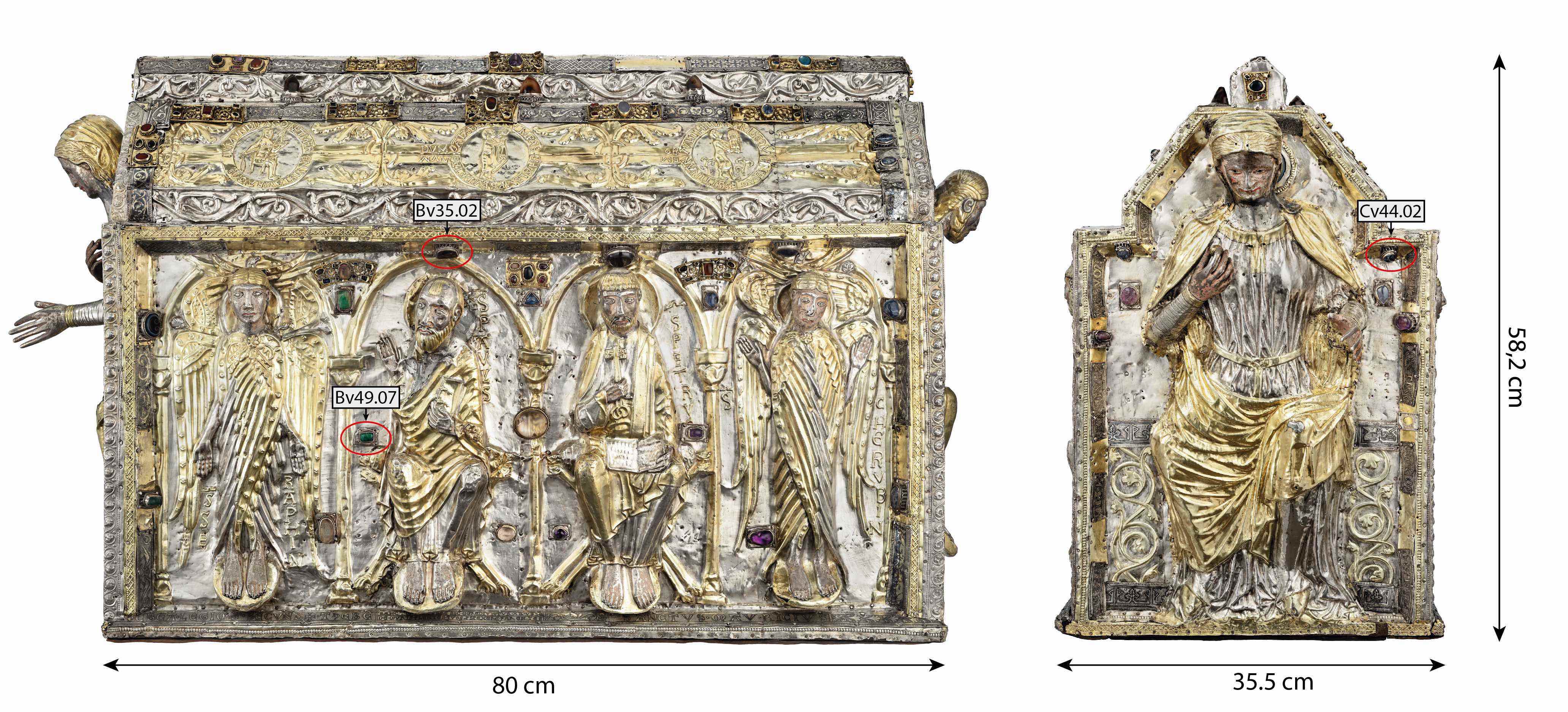
Settings of the Great Shrine of saint Maurice
Romain. Jeanneret (Abbaye de St-Maurice, Saint-Maurice, Valais, Switzerland)
 Credit ABSM, J-Y. Glassey & M. Martinez.
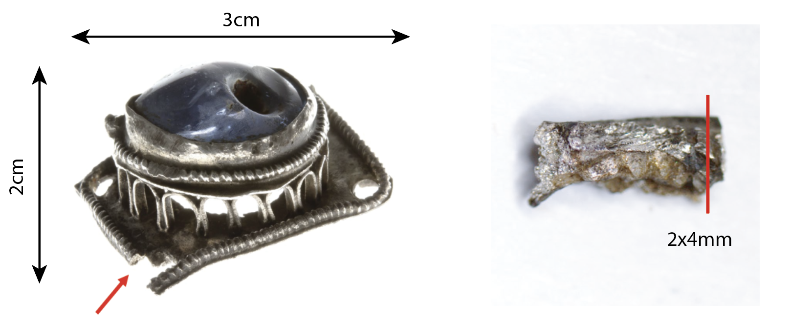
Set of arcature settings from the Great Shrine of saint Maurice. In large quantities (62 pieces) on the reliquary, these decorations have a structure showing a rationalization of the manufacturing process. Openwork plates, twisted wires and folded bands (arcatures) are welded together to form a decorative whole. The surfaces of these mounts seem to indicate a fire passage at the limit of the silver's fusion, which could be attributed to a copper salt soldering since the difference in fusion temperature between the solder and the alloy is very close.
Religious goldsmithing
Northern continental Europe
Between 11th and 13th century
High medieval times
Indoor atmosphere
Abbey of St Maurice, Saint-Maurice, Valais
Abbey of St Maurice, Saint-Maurice, Valais
Inv.2_Settings n°Bv35.02, Bv49.07 and Cv44.02
See Girardin (2015).
 Credit ABSM, R. Jeanneret.
 Credit ABSM, R.Jeanneret.
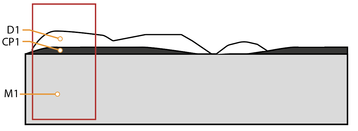
The schematic representation of Fig. 6 gives an overview of the corrosion structures encountered on the arcature settings from a first visual macroscopic observation.
 Credit HEI Arc, S.Ramseyer.
 Credit HEI Arc, S.Ramseyer.
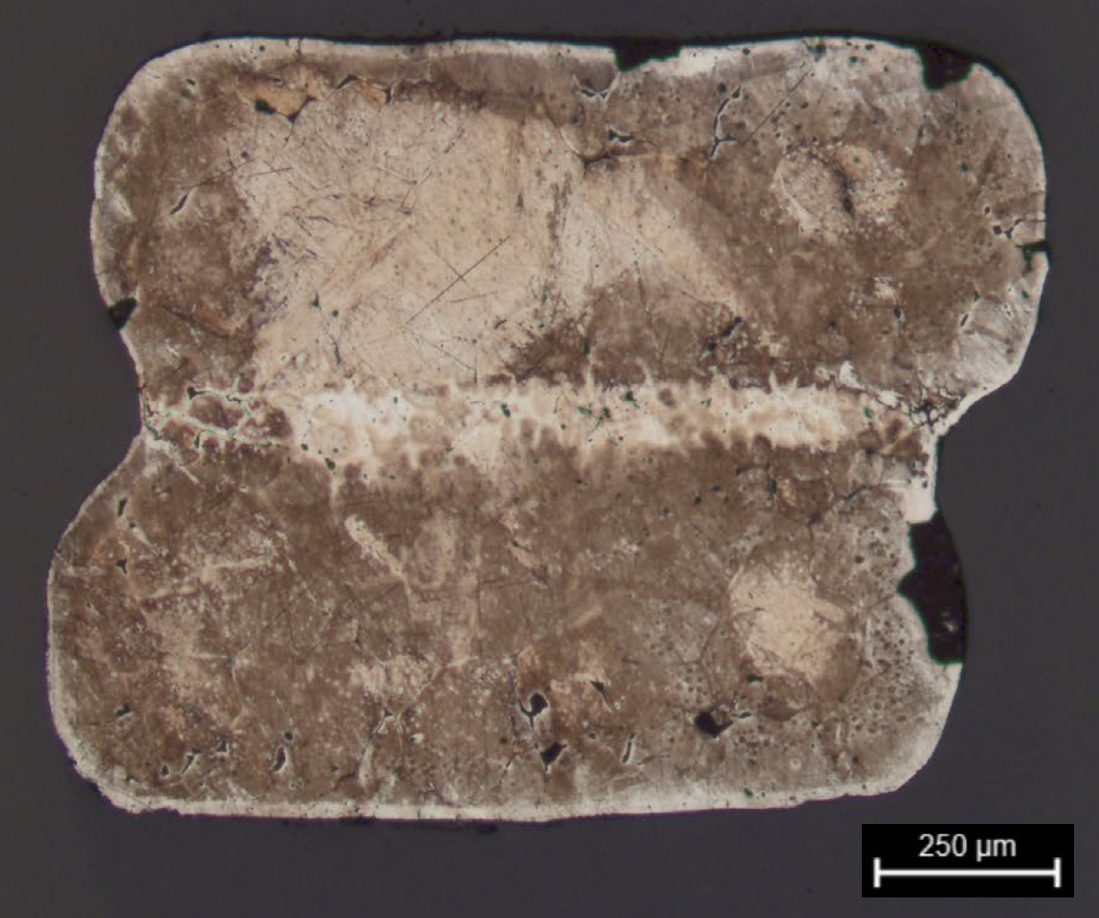
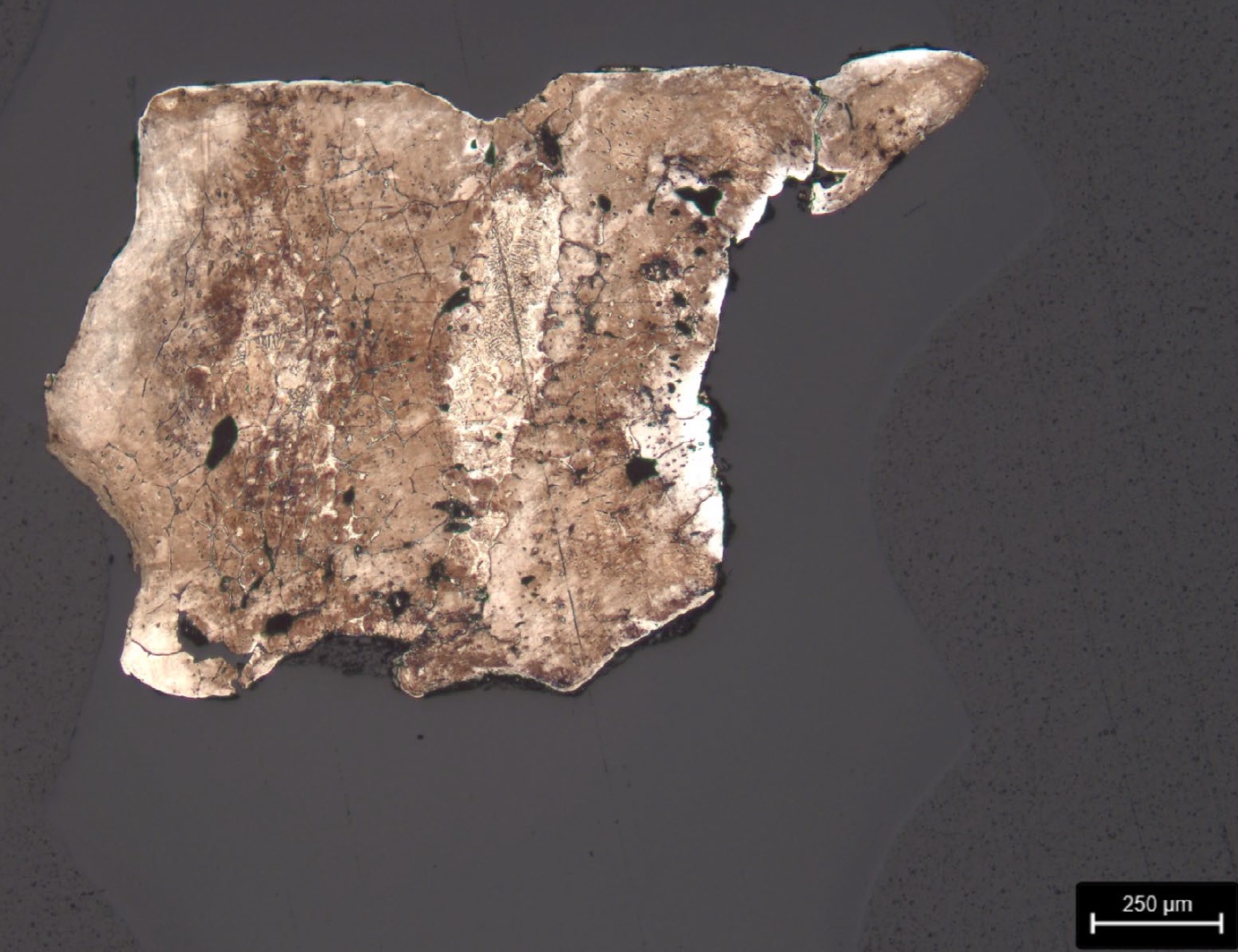
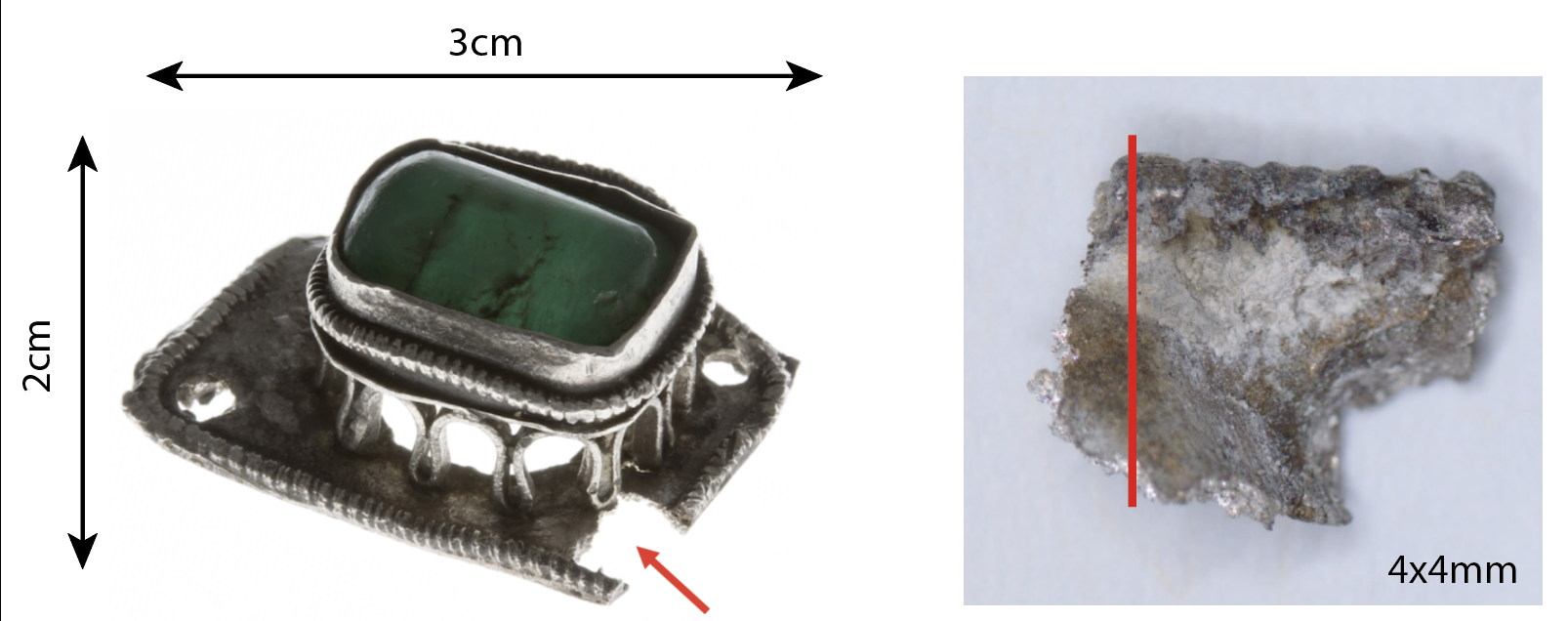
Samples of fragments of arcature settings embedded (Figs. 8 to 10). These are transversal cut as shown on Fig. 3 to 5.
Ag alloy
Hammered, wire twisted, annealed and welded
Abbey of St Maurice, Saint-Maurice, Valais
Abbey of St Maurice, Saint-Maurice, Valais
18.09.2020
None.
Analyses performed:
Non-invasive approach
- XRF with handheld portable X-ray fluorescence spectrometer (NITON XL3t 950 Air GOLDD+, Thermo Fischer®). Precious mode, acquisition time 60s.
Invasive approach (on samples)
- Optical microscopy: the sample is polished, then it is observed on a numerical microscope LEICA DMLM in bright field.
- Metallography: the polished sample is etched in an oxygenated ammoniacal solution (10mL NH3 25%+5mL H2O2 6%+10mL (NH4)2SO4 20%) and observed by optical microscopy in bright field.
- SEM-EDS: the sample is coated with a carbon layer and analyses are performed on a SEM-EDX JEOL equipped with a silicon-drift EDS Oxford detector with an accelerating voltage of 20 kV and probe current from a 1 to 10nA (to reveal the microstructure).
During a portable p-XFR analysis campaign, the base plate of setting number Av35.02 was studied. The result of this analysis seems to indicate a silver alloy of about 3wt% Cu. Traces of elements such as gold, lead, and iron were also found.
The metal of all settings is silver with a low percentage of copper (about 1wt% Cu). It validates XRF analyses. The difference in the percentage of copper compared to the XRF analyses (1wt% vs. 3tw% Cu) can be explained by a better accuracy of this other technique or more likely because it is a different element.
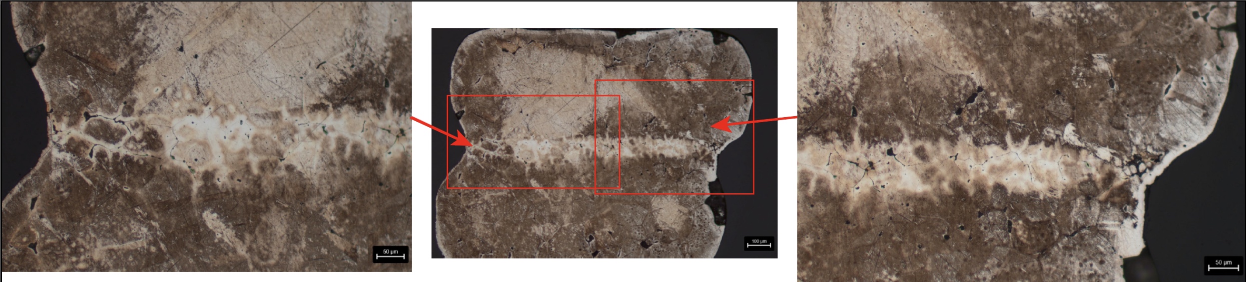
Welding zones are present, in particular for the Bv35.02 and Cv44.02 settings, only visible after etching (Figs. 11, 12 and 15). No clear difference in composition can be seen in these areas (Figs. 13 and 16). The grain structure (large polygonal grains, which may indicate recrystallization of the material(s)) is only visible in the SEM, BSE mode, and by increasing the beam intensity to 10nA (Figs. 8 and 10). Smaller grains are observed in the welding zones (Fig. 8).
 Credit HE-Arc CR, C.Degrigny.
 Credit HEI Arc, S.Ramseyer.
 Credit HE-Arc CR, C.Degrigny.
 Credit HEI Arc, S.Ramseyer.
Recrystallized structure with large grains
Ag
Cu
None.
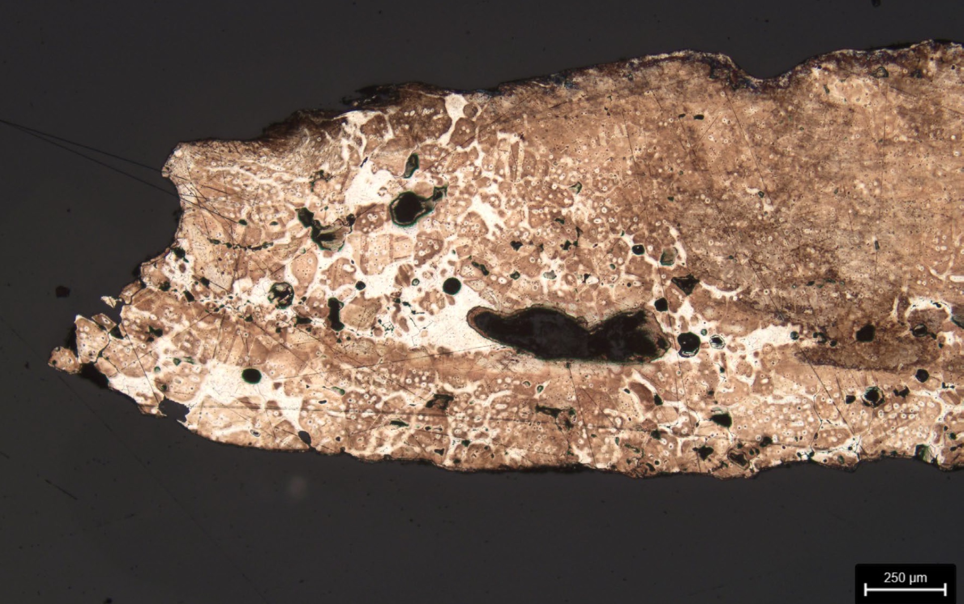
The metal is covered with a thin layer of greyish and yellowish tarnish (CP1) on which residues of cleaning products are detected (D1). This tarnish has not been analyzed, but other work shows that the silver tarnish of the objects in the Treasury of the Abbey of Saint-Maurice usually consists of silver sulphide and silver chloride (Degrigny et al. 2015). This type of tarnishing is typical for silver alloys containing low copper content (Costa 2001, Graedel 1992 and Tissot et al. 2016). The metal of the settings is the site of intergranular corrosion (Wanhill, 2013) which appears to be limited to a thickness of 150-200 microns (Figs. 8 and 10).
intergranular surface corrosion
Silver tarnishing
None.
The observation in cross-section does not allow the identification of the surface deposits observed under the binocular microscope. This is probably due to the fact that they are localized and not very adherent. The surface tarnishing (CP1) is easily recognizable to the eye even though its thickness is very thin and not very visible in cross-section.
The CM1 layer, which corresponds to intergranular corrosion, is only visible in cross-section.
The weld zones are visible under the binocular microscope without being distinguishable from the core metal, but the etched cross-sections confirm their presence and distribution.
The metal is a silver alloy with a low copper content (about 1wt% Cu). Its corrosion layers are typical of silver with a very thin tarnish that has not been analyzed but is considered to be a mixture of silver sulfide and silver chloride. The metal surface suffers from a slight intergranular corrosion.
The metallographic study shows a microstructure that is difficult to interpret as indicated below.
The elemental analysis by EDS does not seem to show a more pronounced presence of copper in the soldered parts. This result goes against the hypothesis that the different parts of the settings would be assembled by soldering with copper salts or brazing by adding a silver pebble whose alloy would be close to the eutectic. Does this mean that the soldering is done without adding copper or silver flakes? This would indicate that the parts are pre-assembled by gluing and then fired at a temperature that places the alloy in a physical situation where welding takes place at the contact points without melting the rest.
This new hypothesis on the manufacture of the settings could explain the appearance of the surfaces of the pieces. Indeed, they seem very damaged, as if they had been heated close to fusion.
References on object and sample
1.Girardin, N. (2015). La châsse de saint Maurice. In: Mariaux, P.A dir., L'abbaye de Saint-Maurice d'Agaune 515-2015. Volume 2 - Le trésor. Ed. Infolio. Gollion, 73-85.
References on analytic methods and interpretation
2.Costa, V. (2001) The deterioration of silver alloys and some aspects of their conservation. In: Studies in Conservation 46 (Supplement-1), 18-34. https://doi.org/10.1179/sic.2001.46.Supplement-1.18.
3.Degrigny, C. et al. (2015) Local cleaning of tarnished Saint Candide reliquary head of the Treasury of Saint-Maurice Abbey, Valais (Switzerland) with the Pleco electrolytic pencil, e-preservation science, 12, 20-27.
4.Graedel, T. (1992). Corrosion mechanisms for silver exposed to the atmosphere, J. Electrochem. Soc. 139, 1963–1970.
5.Northover, S.M. & Northover, J.P. (2014) Microstructures of ancient and modern cast silver–copper alloys. Materials Characterization Volume 90, April 2014, Ed. Elsevier Amsterdam, 173-184.
6.Tissot, I. et al. (2016). Corrosion of silver alloys in sulphide environments: a multianalytical approach for surface characterisation. RSC Advances, 6, 51856-51863, doi:10.1039/C6RA05845K.
7.Wanhill, R. (2013) Stress corrosion cracking in ancient silver, Studies in Conservation, 58:1, 41-49, DOI: 10.1179/2047058412Y.0000000037.