Pin without head HR-18152
Marianne. Senn (Empa, Dübendorf, Zurich, Switzerland) & Christian. Degrigny (HE-Arc CR, Neuchâtel, Neuchâtel, Switzerland) & Naima. Gutknecht (HE-Arc CR, Neuchâtel, Neuchâtel, Switzerland) & Rémy. Léopold (HE-Arc CR, Neuchâtel, Neuchâtel, Switzerland)
 Credit Laténium, after Rychner-Faraggi, 1993.
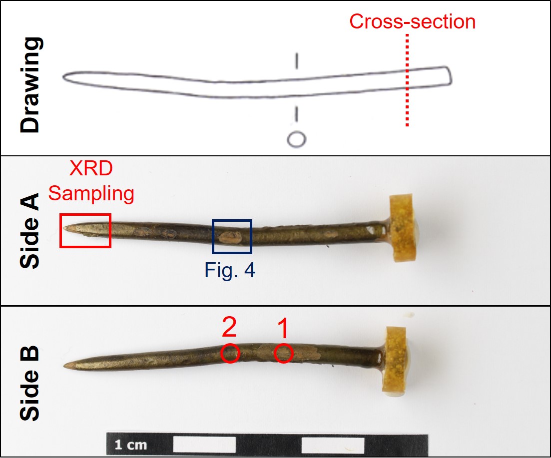
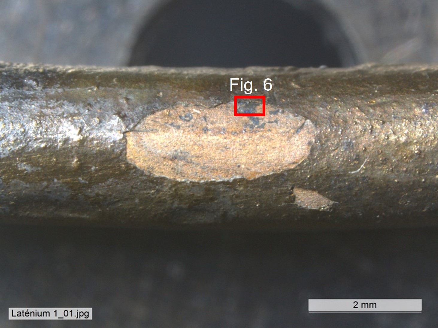
Pin without head and smooth brown-yellow corrosion products (Figs. 1-2). Dimensions: L = 7,5cm; Ø = 3.3mm; WT = 4g.
Jewellery
Hauterive - Champréveyres, Neuchâtel, Neuchâtel, Switzerland
Excavation 1983-1985, object from layer 3 to 5
Late Bronze Age
Hallstatt B1 (1054/1037BC _ 1000BC)
Lake
Laténium, Neuchâtel, Neuchâtel
Laténium, Neuchâtel, Neuchâtel
Hr 18152
N/A
The object was sampled in 1987 for analysis by Schweizer. Documentation of the strata in binocular mode on the remaining fragment of the object was performed in 2022.
 Credit HE-Arc CR, N.Gutknecht/L.Rémy.
 Credit HEI Arc, S.Ramseyer.
 Credit Laténium, C,Cevey.
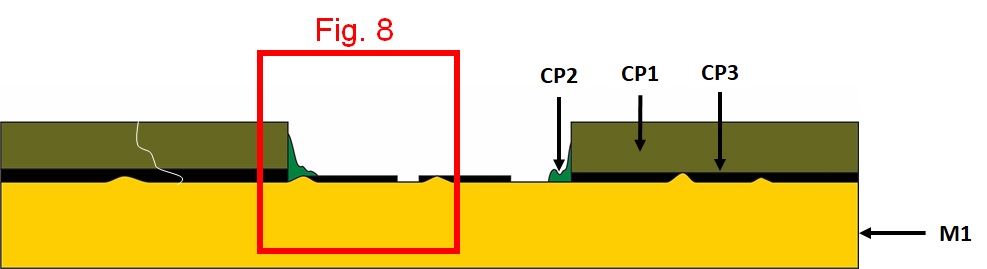
The schematic representation below gives an overview of the corrosion structure encountered on the pin from a first visual macroscopic observation.
| Strata | Type of stratum | Principal characteristics |
| CP1 | Corrosion product |
Layer, olive green, metallic, medium thickness, compact, tough, soft |
| CP2 | Corrosion product | Nodule, light green, thin, scattered, non compact, powdery, very soft |
| CP3 | Corrosion product | Black, thin, scattered, compact, friable, soft |
| M1 | Metal | Dark yellow, thick, continuous, compact, tough, soft |
Table 1: Description of the principal characteristics of the strata as observed under binocular and described according to Bertholon's method.
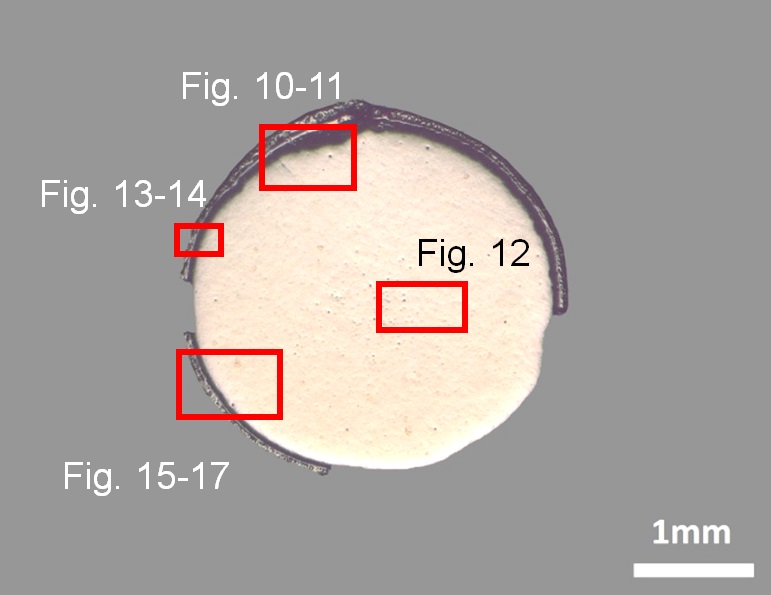
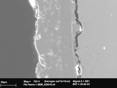
The cross-section is circular and is a complete section through the pin (Fig. 3). It is covered with a rather thin and regular (in thickness) corrosion layer (Fig. 6). On the sample, one third of the corrosion layer is missing (Fig. 9).
Tin Bronze
Annealed after cold working
MAH 87-194
Laténium, Neuchâtel, Neuchâtel
Laténium, Neuchâtel, Neuchâtel
1987, metallography and corrosion characterisation
This sample is mentioned in Schweizer, 1994. It was taken in 1987 and there is no photographic documentation of the object before cutting and sampling.
Analyses performed:
Non-invasive approach
XRF with handheld portable X-ray fluorescence spectrometer (NITON XL5). General Metal mode, acquisition time 60s (filters: Li20/Lo20/M20).
Invasive approach (on the sample)
Metallography (etched with ferric chloride reagent), Vickers hardness testing, XRF, ICP-OES, SEM/EDS, XRD, Raman spectroscopy (conditions provided in the About tab of the MiCorr application).
XRF analyses of the pin were carried out on two representative areas (Fig. 3). Point 1 was done in a lacuna of the brown-yellow corrosion layer, while point 2 was performed on the brown corrosion layer (CP1) where all strata (soil, corrosion products, and metal) are analyzed at the same time.
The metal is presumably a tin bronze alloy. The other elements detected are : S, Fe, Si, Al, Pb, Sb, As, Ag, Zn, Ni.
Results of point 2 are very different from those of point 1, they indicate the surface enrichment in Fe and in S and the depletion in Cu.
| Elements (mass %) | Cu | Sn | S | Fe | Si | Al | Pb | Sb | As | Ag | Zn | Ni | |||||||||||||
| % |
+/-2σ |
% | +/-2σ | % | +/-2σ | % | +/-2σ | % | +/-2σ | % | +/-2σ | % | +/-2σ | % | +/-2σ | % | +/-2σ | % | +/-2σ | % | +/-2σ | % | +/-2σ | TOTAL | |
| 1 | 78.5 | 0.13 | 7.5 | 0.04 | 6.5 | 0.05 | 4.0 | 0.04 | 1.5 | 0.01 | 0.5 | 0.11 | 0.2 | 0.01 | 0.2 | 0.01 | 0.2 | 0.02 | 0.1 | 0.02 | <0.1 | <0.01 | <0.1 | 0.01 | 99.7 |
| 2 | 39.0 | 0.1 | 5.0 | 0.03 | 26.0 | 0.08 | 30.0 | 0.08 | 0.3 | 0.03 | <LD | <LD | <0.1 | 0.01 | 0.1 | 0.01 | <0.1 | 0.01 | <0.1 | 0.02 | 0.1 | 0.02 | <LD | <LD | 100.5 |
Table 2: Chemical composition of the surface of the pin at two representative points shown in Fig. 3. Method of analysis: XRF, UR-Arc CR.
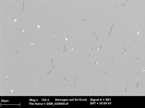
ICP-OES analyses of the remaining metal show a tin bronze as suggested in Table 1 (point 1). The metal also has copper sulphide as well as heavy metal (Pb-rich) inclusions (Figs. 10 and 11). Close to the surface of the remaining metal, copper sulphide inclusions are elongated and form rows (Fig. 10). The etched structure of the tin bronze shows polygonal grains; some of them are twinned (Fig. 12). In the centre of the sample and on the edges, the grains are smaller. The copper sulphide inclusions are located at the grain boundaries and in the grains. The average hardness of the metal is about HV1 110.
| Elements | Cu | Sn | Pb | Sb | As | Ag | Fe | Ni | Co | Zn |
| mass% | 89.22 | 9.57 | 0.34 | 0.26 | 0.19 | 0.15 | 0.09 | 0.05 | 0.06 | 0.05 |
Table 3: Chemical composition of the metal. Method of analysis: ICP-OES, Laboratory of Analytical Chemistry, Empa.
 Credit HE-Arc CR.
 Credit HE-Arc CR.
Polygonal and twinned grains
Cu
As, Ag, Sn, Sb, Pb
Schweizer (1994) indicates that the copper-tin alloys similar to the one of the pin have minor constituents that were certainly not added intentionally. Furthermore, he mentions that there is no systematic composition difference between bronzes with a lake patina and those with a land patina.
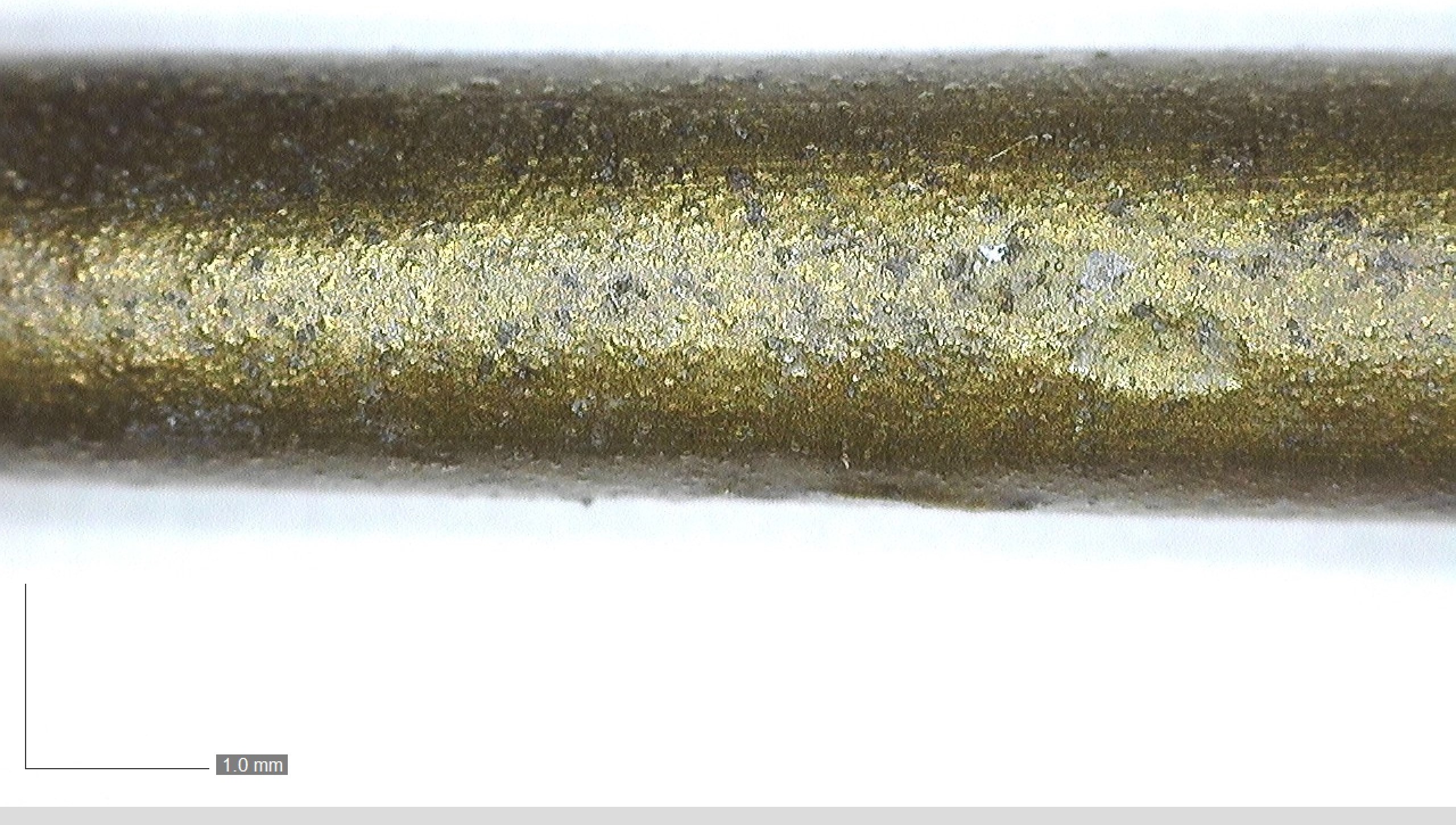
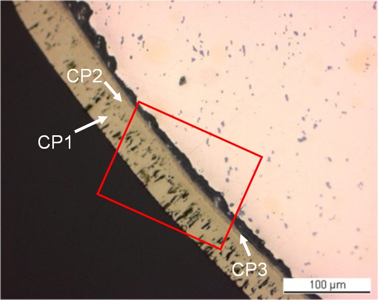
The corrosion layer is regular in thickness (around 50µm, Figs. 5 and 6). It presents lacuna (Fig. 4) and in some areas it is missing completely. At the metal - corrosion layer interface, there is a crack showing that the latter has separated from the metal core along its whole length (Figs. 6, 9, 10, 13 and 14). The corrosion layer can be divided into three distinct strata (CP1-3): directly above the crack is a first dense but cracked and irregular inner layer (CP3, Figs. 6, 13 and 14). In bright field it appears brown (Fig. 15), in normal and polarised light dark brown (Fig. 16). It is separated from the adjacent layer by a clear line (Figs. 14 and 15). The second layer (CP2) is dense with little porosity (Figs. 13 and 14). In bright field it appears light brown (Fig. 15), in polarised light dark yellow (Fig. 16). The third and outermost layer (CP1) appears light brown under normal light (Fig. 2) and in bright field (Fig. 15), contains particles (Fig. 14) and is very porous (visible as golden reflections under polarized light, Fig. 16).
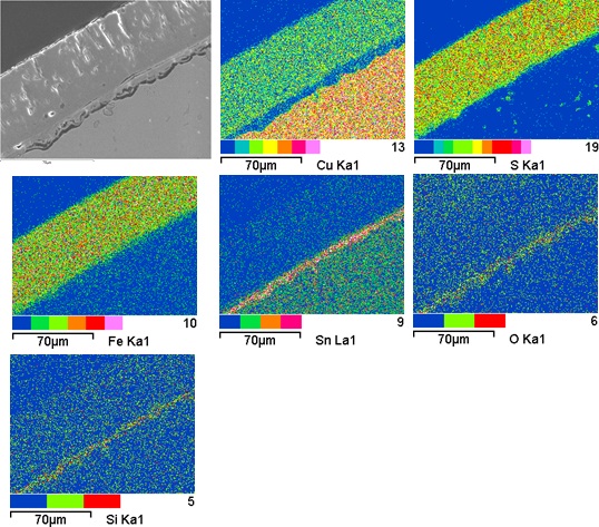
These results are entirely consistent with Schweizer's observations (Schweizer 1994). The elemental chemical distribution of the SEM image selected reveals that the inner layer (CP3) is depleted in Cu, but rich in Sn,O and Si (Fig. 17 and Table 4) and its interface with the intermediate layer (CP2) could represent the limit of the original surface (Figs. 14 and 17). The second and third layer (CP2 and CP1) are Fe, Cu and S-rich (Fig. 17) and have a composition similar to chalcopyrite/CuFeS2 as suggested in Table 2 (point 2). This was confirmed by XRD. The particles (inclusions) have a composition similar to covelline or covellite/CuS (Table 4). Both chalcopyrite and covelline have been identified by Raman spectroscopy (Figs. 18 and 19).
| Elements | S | Fe | Cu | O | Si | Sn | Total |
| CP1 and CP2 | 35 | 30 | 34 | < | < | < | 99 |
| Particles in CP1 | 26 | 4.1 | 68 | < | < | < | 98 |
| CP3 | 5.8 | 5.0 | 13 | 32 | 2 | 41 | 99 |
Table 4: Chemical composition (mass %) of the corrosion layers from Fig. 15. Method of analysis: SEM/EDS, Laboratory of Analytical Chemistry, Empa.
 Credit HE-Arc CR.
 Credit HE-Arc CR.
 Credit HE-Arc CR.
 Credit Empa.
 Credit SNM.
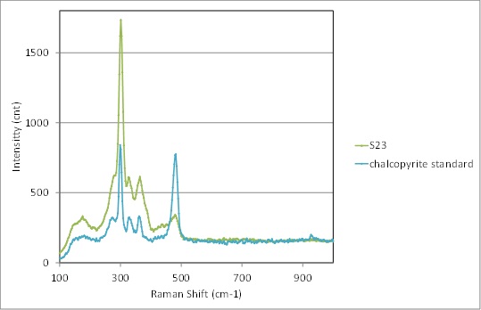
Fig. 18: Raman spectrum of the outermost layer (S23) of Fig.14 compared to a chalcopyrite standard spectrum. Settings: laser wavelength 532nm, acquisition time 50s, 4 accumulations, filter D2 (0.75-0.8mW), hole 1000, slit 100, grating 600. Method of analysis: Raman spectroscopy, Lab of Swiss National Museum, Affoltern a. Albis ZH,
 Credit SNM.
Fig. 19: Raman spectrum of the inclusions of the outermost layer (S42) of Fig. 14 compared to a covelline / covellite standard spectrum. Settings: laser wavelength 532nm, acquisition time 10s, 5 accumulations, D2 (0.75-0.8mW), hole 500, slit 80, grating 600. Method of analysis: Raman spectroscopy, Lab of Swiss National Museum, Affoltern a. Albis ZH,
Passive
lake patina (Schweizer 1994)
Schweizer (1994) indicates that CP1 shows evidence of pseudomorphic replacement of metal grains by corrosion products that we did not observe.
CP1 in binocular mode is documented as CP1 and CP2 in cross-section mode.
CP2 in binocular mode is not observed in cross-section mode, as the observation was made over an area where this layer is absent.
CP3 in binocular mode matches CP3 in cross-section mode.
On cross-section, it was possible to describe and analyze the microstructure of the metal.
The pin is made from a tin bronze and has been annealed after cold working. It is covered with a regular, dense brown-yellow corrosion layer, called lake patina by Schweizer (Schweizer, 1994). The inner, thin Sn-rich corrosion layer contains soil elements such as Si. The brown-yellow, thick intermediate and outer corrosion layers have the composition of chalcopyrite. The limit of the original surface can be located between the chalcopyrite and the Cu depleted but Sn-rich inner corrosion layer. The corrosion is a type 1 according to Robbiola et al. 1998. According to Schweizer's research, chalcopyrite can only be generated in the presence of sulfate-reducing bacteria. Conditions for those bacteria are an anaerobic, humid, and S and Fe-rich environment. This object was probably abandoned directly into the lake.
References on object and sample
Object files in MiCorr
1. MiCorr_Pin or needle fragment HR-3031
2. MiCorr_Tang fragment of a knife HR-6567
3. MiCorr_Tang fragment of a knife HR-6246
4. MiCorr_Pin HR-17773
5. MiCorr_Pin HR-3071
6. MiCorr_Pin HR-18603
7. MiCorr_Pin HR-3389
References object
8. Rychner-Faraggi A-M. (1993) Hauterive – Champréveyres 9. Métal et parure au Bronze final. Archéologie neuchâteloise, 17 (Neuchâtel).
9. Hochuli, S. et al. (1988) SPM III Bronzezeit , Verlag Schweizerische Gesellschaft für Ur- und Frühgschichte Basel, 76-77, 379.
References sample
10. Empa Report 137 695/1991, P.O. Boll.
11. Rapport d'examen, Lab. Musées d'Art et d'Histoire, Geneva GE, 87-194 à 87-197.
12. Schweizer, F. (1994) Bronze objects from Lake sites: from patina to bibliography. In: Ancient and historic metals, conservation and scientific research (eds. Scott, D.A., Podany, J. and Considine B.B.), The Getty Conservation Institute, 33-50.
References on analytic methods and interpretation
13. Robbiola, L., Blengino, J-M., Fiaud, C. (1998) Morphology and mechanisms of formation of natural patinas on archaeological Cu-Sn alloys, Corrosion Science, 40, 12, 2083-2111.