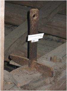
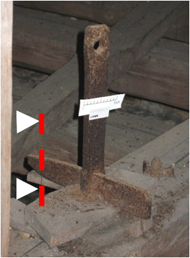
Wedge part of an altar crown suspension
Marianne. Senn (EMPA, Dübendorf, Zurich, Switzerland) & Christian. Degrigny (HE-Arc CR, Neuchâtel, Neuchâtel, Switzerland)
Construction steel used for suspension.
Wedge part of an altar crown suspension in the abbey chapel
Abbey of Rheinau, Zürich, Zurich, Switzerland
1720 AD
Modern Times
1720 AD
Indoor atmosphere
Abbey of Rheinau, Zürich, Zurich
Canton of Zurich, Zurich
None (3)
Not conserved (machine brushed)
Stratigraphic representation: none
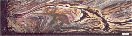
This sample is a section from the end of the wedge. The corrosion crust appears on the top side on Fig. 3.
P-rich iron and hypoeutectoid steel
Annealed after (hot) rolling
RHE1-NR
Empa (Marianne Senn)
IWT (Naila Hadzic), Wallisellen, Zurich
January 2008, material testing and security report
Analyses performed:
Metallography (nital etched and etched with Oberhoffer’s reagent), Vickers hardness testing, LA-ICP-MS, SEM/EDX.
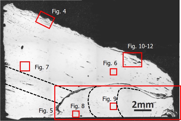
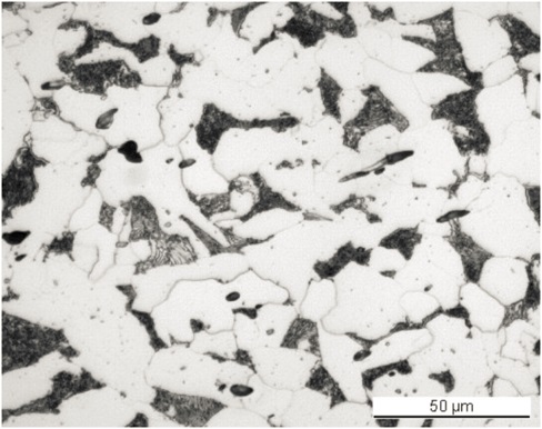
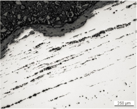
The remaining metal is a P-rich iron (0.3-0.45 mass%) with two zones consisting of soft, hypoeutectoid steel (C content 0.2 mass%) (Fig. 3 and Table 1). The P-rich iron contains many elongated slag inclusions of various sizes forming parallel rows (Figs. 3 and 4). The number of slag inclusions is higher than in bloomery iron and their distribution is typical for rolled metal. A crack, partially filled by hammer scale and corrosion products, indicates a poor quality welding seam (Fig. 3). Below the inclusions the curve produced by forging is highlighted. In good quality wrought iron slag inclusions are small, uniformly distributed and have identical compositions (Boesenberg 2006, 622). This is not the case in this sample, but can be explained by the rudimentary rolling process of the 18th century. The chemical composition of the slag inclusions shows that iron oxides dominate, beside phosphorus oxide, calcium oxide and silica (Table 2). The composition is typical for slag formed by hearth refining of pig iron (Dillmann and L'Héritier 2007). During this process, the pig iron is oxidised. The oxidising elements are Si, P, Mn, V and Cr. The analyzed slag inclusions contain more Fe than most published ones. The high P content is similar to published examples from the 18th century (Dillmann and L'Héritier 2007, 1820). The high calcium oxide content, which is often combined with high silica content, could originate from the addition of both materials while refining the pig iron to better eliminate the P. In one of our measurements, only the silica concentration is high (Table 2). This can be interpreted as resulting from the addition of sand during forging. Etching with Oberhoffer’s reagent outlines the thick welding seam (Fig. 5), the rolling direction and the P segregation. Etching with nital mainly shows a ferritic structure (Fig. 6). The grains vary in size (between ASTM grain sizes of 4 to 8) and are recrystallized. The ferrite shows local ghost structures, and includes Neumann bands and some needles (Figs. 7 and 8). These are typical structures of P-rich iron. The ghost structure is formed by a fast recrystallization of P-rich iron after heating above 1000°C. The Neumann bands indicate cold working. The hypoeutectoid steel consists of ferrite with lamellar pearlite (Fig. 9). The average hardness of the metal is HV1 185 (in the Empa test report a mean of HV10 175 was determined). The areas close to the welding seam are harder (ca. HV1 210). The calculated tensile strength based on HV10 175 is about 544N/mm2.
| Elements | Ni/Co | Al | P | Ti | V | Cr | Mn | Co | Ni | Cu | As | Mo | Ag | Sn | Sb | W | C* mass% |
|---|---|---|---|---|---|---|---|---|---|---|---|---|---|---|---|---|---|
| Median mg/kg | 3.1 | < | 3400 | < | 40 | 80 | 20 | 270 | 840 | 340 | 400 | 20 | < | 10 | 10 | < | 0-0.2 |
| Detection limit mg/kg | - | 4 | 65 | 8 | 1 | 10 | 2 | 1 | 3 | 1 | 2 | 3 | 1 | 0.4 | 1 | 3 | - |
| RSD % | 3 | 1 | 16 | - | 168 | 55 | 114 | 6 | 6 | 7 | 19 | 7 | - | 17 | 22 | - | - |
*visually estimated
Table 1: Chemical composition of the P-rich iron. Method of analysis: LA-ICP-MS, Lab Inorganic Chemistry, ETH.
| Structure of inclusion | Env | MgO | Al2O3 | SiO2 | P2O5 | SO3 | K2O | CaO | TiO2 | V2O5 | Cr2O3 | MnO | FeO | Total |
SiO2/Al2O3 |
|---|---|---|---|---|---|---|---|---|---|---|---|---|---|---|---|
| n. d. | steel | 0.8 | 0.7 | 6.1 | 23 | < | < | 9.0 | < | 1.9 | 1.7 | 0.7 | 60 | 105 | 8.3 |
| Glassy matrix | steel | 1.4 | < | 17 | 18 | < | < | < | < | < | < | 0.7 | 66 | 105 | 67 |
| White plates (wustite) | steel | < | < | 1.1 | < | < | < | < | 0.9 | < | < | < | 97 | 101 | 3.4 |
| Droplet (wustite) | steel | < | 1.3 | 0.9 | 1.1 | < | < | 0.6 | < | 2.4 | < | < | 99 | 106 | 0.7 |
|
Slag with plates and droplets |
steel | 1.0 | 0.6 | 12 | 21 | < | < | 2.7 | < | 0.6 | < | < | 69 | 107 | 20 |
| n. d. | steel | 0.8 | 2.0 | 12 | 29 | 1.0 | 1 | 14 | 0.6 | < | < | 1 | 47 | 109 | 5.7 |
| Wustite in glass | P-rich iron | 0.6 | 0.7 | 6.5 | 17 | 0.8 | < | 4.0 | < | 0.9 | < | 0.9 | 77 | 109 | 9.2 |
| n. d. | P-rich iron | < | 0.8 | 1.3 | 4.6 | < | < | < | 0.6 | 3.0 | 1.5 | < | 94 | 106 | 1.6 |
| n. d. | P-rich iron | 0.8 | 1.1 | 5.4 | 11 | < | < | 3.8 | 0.9 | 3.9 | < | 0.7 | 81 | 108 | 5.1 |
| n. d. | P-rich iron | < | 1 | 1.6 | 3.7 | < | < | 0.8 | 0.8 | 5.3 | 0.7 | < | 84 | 99 | 1.6 |
| n. d. | P-rich iron | 1.2 | < | 8.9 | 13 | < | < | 2.7 | < | 2.3 | 0.7 | 0.9 | 68 | 99 | 18 |
| n. d. | P-rich iron | 0.8 | 1.2 | 8.7 | 23 | < | 9.8 | < | 0.7 | < | 1.3 | 54 | 99 | 7.6 |
Table 2: Chemical composition of the slag inclusions (mass %). Method of analysis: SEM/EDX, Laboratory of Analytical Chemistry, Empa.
 Credit HE-Arc CR.
 Credit HE-Arc CR.
 Credit HE-Arc CR.
 Credit HE-Arc CR.
 Credit HE-Arc CR.
Recrystallized grains, Newman bands, ghost structure
Fe
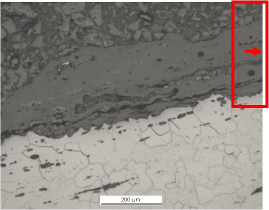
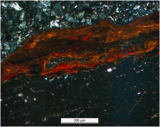
The corrosion crust is thin and irregular. It is restricted to one of the three surfaces. In bright field, the corrosion layer seems homogeneous and appears medium-grey with a fissure parallel to the metal surface (Fig. 10). Under polarised light the corrosion products near the metal surface are mostly red-orange, whereas in the outer layer they appear orange-brown (Fig. 11). A dark-brown zone is visible between them and contains bright inclusions with a chemical composition similar to wüstite (Table 3). This corresponds to corroded slag inclusions (internal markers). Chemical analysis (Table 3) and elemental mapping (Fig. 12) do not highlight a difference in composition of the corrosion layers, except for the corroded slag inclusions.
|
Elements |
O | S | Fe | Total |
|---|---|---|---|---|
| Inner part, dark-brown corrosion layer (CP2i) | 34 | < | 61 | 96 |
| Inner part, orange corrosion products (average of 2 similar analyses) (CP3i) | 34 | < | 64 | 99 |
| Bright inclusion | 23 | 83 | 106 | |
| Middle, orange corrosion products | 36 | 0.6 | 64 | 101 |
| Outer orange corrosion layer (average of 3 similar analyses) (CP1e) | 34 | 0.7 | 62 | 96 |
Table 3: Chemical composition (mass %) of the corrosion crust (from Fig. 11). Method of analysis: SEM/EDX, Laboratory of Analytical Chemistry, Empa.
 Credit HE-Arc CR.
 Credit HE-Arc CR.
Uniform - pitting
?
Corrected stratigraphic representation: none
The wedge was rolled, hammered and annealed from a refined, P-rich wrought iron. It was welded from at least two parts. The C distribution is irregular and shows a zone of soft steel in the middle of the iron. The indoor corrosion seems superficial, but it is possible that the sample surface was cleaned before embedding (Hadzic 2008).
|
References on object and sample |
|
References sample 1. Hadzic, N. (2008), Prüfbericht Nr. 448’051, Empa.
|
|
References on analytic methods and interpretation |
| 2. Boesenberg, J.S. (2006) Wrought iron from the USS Monitor: mineralogy, petrology and metallography. Archaeometry 48-4, 613-631. 3. Dillmann, P., L'Héritier, M. (2007) Slag inclusions analyses for studying ferrous alloys employed in French medieval building: supply o materials and diffusion of smelting process. Journal of Archaeological Science 34, 1810-1823. |