Axe head N11
Christian. Degrigny (HE-Arc CR, Neuchâtel, Neuchâtel, Switzerland) & Valentin. Boissonnas (HE-Arc CR, Neuchâtel, Neuchâtel, Switzerland)
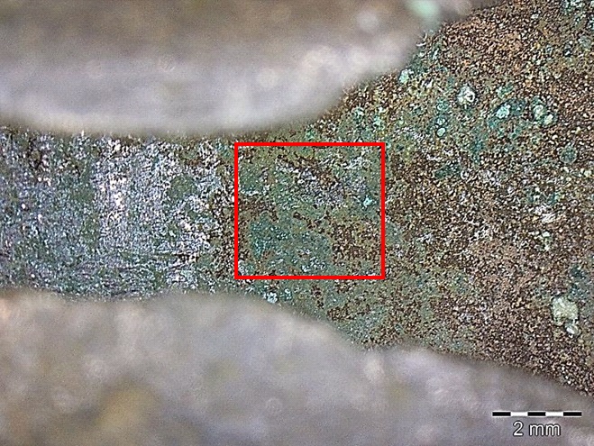
Bronze axe head covered with a brown patina (Fig. 1). A uniform darker green corrosion product as well as a green powdery corrosion product appear locally in some areas. Dimensions: L = 90 mm; W max = 40 mm ; WT = 154.32 g.
Tool
Unknown
Date unknown
Middle Bronze Age
Bronze Age
Soil
Neues Museum, Biel/Bienne
Neues Museum, Biel/Bienne
N11
No information, the object might have been treated in the past.
Nothing to report.
 Credit HE-Arc CR, E.Forster.
 Credit HE-Arc CR, E.Forster.
 Credit HE-Arc CR, E.Forster.
 Credit HE-Arc CR, E.Forster.
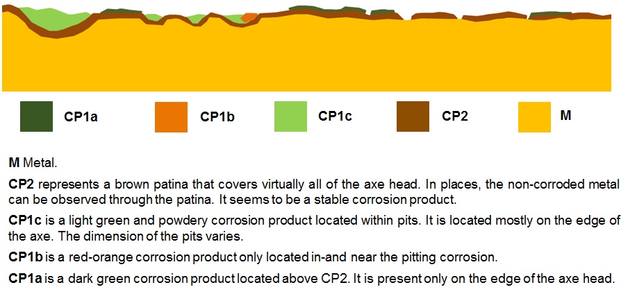
The schematic representation below gives an overview of the corrosion layers encountered on the head axe from a first visual macroscopic observation.
Particles were sampled (Figs. 4-7 and Fig. 9) with a scalpel from the areas where local corrosion has developed.
Tin Bronze
Unknown
-----
HE-Arc CR, Neuchâtel, Neuchâtel
HE-Arc CR, Neuchâtel, Neuchâtel
March 04, 2013, chemical and structural analysis
Nothing to report.
Analyses performed:
SEM-EDS, FTIR.
The FTIR device used is a Biorad Excalibur FTS 3000 spectrometer coupled to an IR microscope UMA500. The measurements were performed between 4000 and 650 cm-1.
SEM/EDS analysis of corroded particles indicates that the alloy is composed of copper (Cu) and tin (Sn) with some arsenic (As). The core metal is most likely a tin bronze.
?
Cu
As, Sn
Nothing to report.
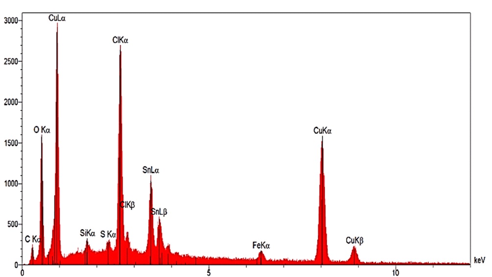
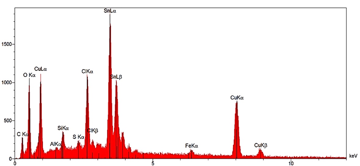
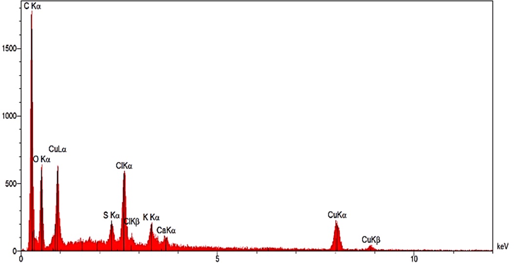
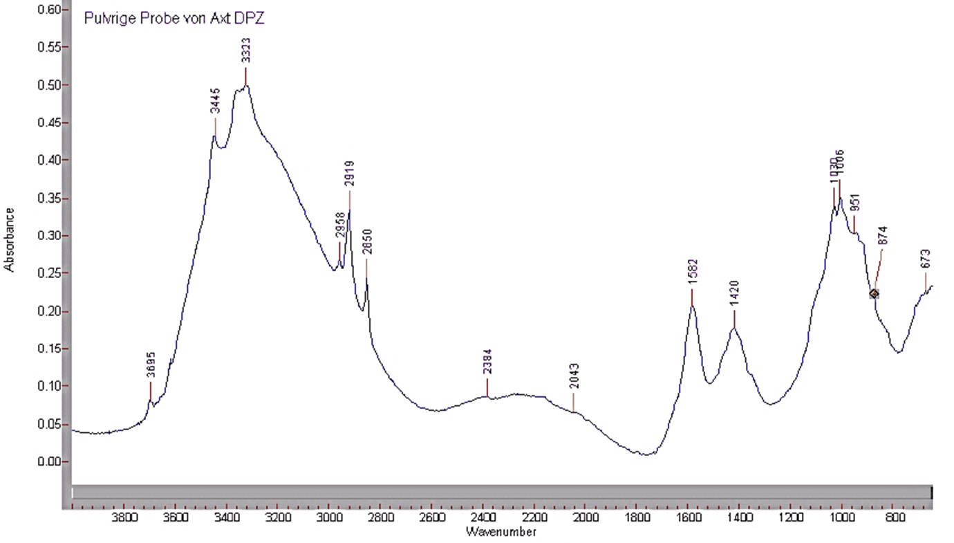
Analyses by SEM/EDS indicate that the light yellow particles of sample 1 are predominantly composed of Sn and O with minor presence of C, Cu, Fe, S, Cl and As (Fig. 12), while the green and red particles of sample 2 are respectively composed of O, Cu, Cl, and Sn, with a minor presence of Fe and S (Fig. 13) and Cu, O (Fig. 14, possibly cuprite). Sample 3 consists of green particles composed mostly of Sn, Cl, Cu and O with S, Al and Fe as minor elements (Fig. 15). Sample 4 is constituted of green and white particles. The former have the same composition as the particles of sample 3 while the white particles are significantly different in composition: containing a large amount of C with a small amount of O, Cl, S, K and Cu (Fig. 16). The FTIR spectrum of the white particles (Fig. 17) shows several characteristic peaks of an organic compound: 2919 cm-1 and 2850 cm-1 (C-H- bond), 3445 cm-1 and 3323 cm-1 (O-H- bond) or 1030cm-1, 1006cm-1 and 951cm-1 (C-O-C- bond).
Table 1: Identification of chemical elements in the corrosion products on the head axe. Method of analysis: SEM/EDS, HEI-Arc.
|
|
Sample / particles |
Major elements |
Minor elements |
|
Green powdery corrosion product |
Sample 1 |
Sn + O |
C + Cu + Fe + S + Cl + As |
|
Sample 2 – CP1c (Fig. 10) - Green particles |
O + Cu + Cl + Sn |
Fe + S |
|
|
Sample 2 – CP2 (Fig.10) - Red-brown particles |
Cu + O |
|
|
|
Sample 3 - CP1c (Fig. 10) |
Sn + Cl+ Cu + O |
S + Al + Fe |
|
|
Darker green corrosion product |
Sample 4 – CP1a (Fig. 11) - Green particles |
Cl + Sn + Cu + O |
S + C |
|
Sample 4 – CP1a (Fig. 11) - White particles |
C |
O + Cl + S + K + Cu |
Multiform - pitting
None
Nothing to report.
The schematic representation of corrosion layers below integrates additional information based on the analyses carried out.
The axe head is probably a tin bronze containing a small amount of As. It is difficult to interpret the corrosion layer only by macroscopic observation. The analyses show that all green corrosion products contain chlorides that might originate from strip-cleaning by hydrochloric acid (although not documented). Active corrosion is not proved but we suspect the presence of atacamite, paratacamite or clinoatacamite (Cu2Cl(OH)3). FTIR revealed the presence of an organic compound on the metal surface (possibly a protective coating).
|
References on analytic methods and interpretation 1. Bertholon, Régis. La limite de la surface d’origine des objets métalliques archéologiques. Caractérisation, localisation et approche des mécanismes de conservation. ©Régis Bertholon, Paris, 2000. 2. Degrigny, Christian and Senn, Marianne. Methodology to study and analyse the microstructures and corrosion forms of ancient and historic metals: application to metallographic samples from Swiss collections MIFAC-Métal. Projet Sagex, Final Report, Haute école de conservation-restauration ARC, Neuchâtel, 2012. 3. Selwyn, Lyndsie. Métaux et corrosion Un manuel pour le professionnel de la conservation. Institut Canadien de Conservation, Ottawa, 2004. |