Domed cap nut
Christian. Degrigny (HE-Arc CR, Neuchâtel, Neuchâtel, Switzerland) & Mathea. Hovind (University of Oslo, Department of archaeology, conservation and history (IAKH-UiO), Oslo, Oslo, Norway)
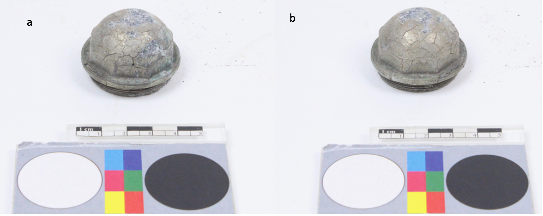
A domed, threaded fitting, consisting of a cast alloy with a metallic plating (Fig. 1). Its shape is octagonal and the inside is hollow. The plating is heavily cracked, leading to surface flaking. The metal appears to be consumed by some kind of internal corrosion. Dimensions: L (ø) = 40mm; H = 28mm; T = 5mm; WT = 49g.
Cap
Château de Germolles, Mellecey, Bourgogne, France
Date unknown
Modern Times
19th - 20th century
Outdoor atmosphere
Haute Ecole Arc Conservation-Restauration
Château de Germolles, Mellecey, Bourgogne
Not registered.
No conservation data recorded.
Nothing to report.
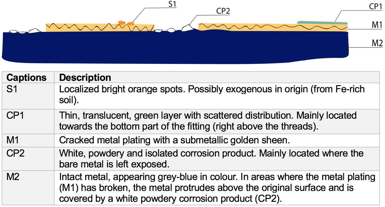
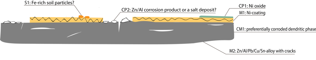
The schematic representation below (Fig. 3) gives an overview of the corrosion layers encountered on the object from a first visual macroscopic observation.
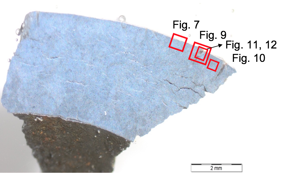
The sample is a cross section of the metal, representative of the head of the fitting. It shows external cracks extending from the metal surface and into its structure in addition to internal cracks, visible as thin lines along its longitudinal axis (Fig. 4).
Zn Al Sn Cu Alloy
None
NZC2018 (Ni/Zn Cap, sampled in 2018)
HE-Arc CR, Neuchâtel, Neuchâtel
Haute Ecole Arc Conservation-Restauration
March 2018, study of corrosion stratigraphy and chemical analyses
The fact that the artefact was considered as test material enabled extensive sampling that would not otherwise be possible.
Metallography
Microscope: Leica DMi8 (a metallographic, inverted, reflected light microscope) with magnification up to 500X. Camera: Olympus SC50 connected to the software “Olympus Stream”, version 1.9.4. Illumination modes: bright field and cross-polarized light.
SEM-EDS
Instrument: Jeol 6400; voltage: 20 kV; working distance: 18 and 24mm; sample preparation: palladium depot.
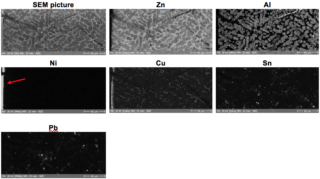
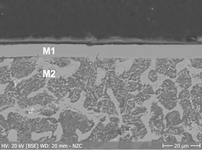
The metal of the domed fitting (M2) consists of a Zn/Al/Pb/Cu/Sn alloy (Table 1) externally covered by a nickel-based plating (M1) (Figs. 7 and 8). The bulk metal (M2) has a dendritic microstructure appearing light grey in bright field, while the interdendritic phase appears white (Fig. 9). The latter is Zn-rich, while the dendritic phase consists of approximately equal amounts of Zn and Al (Table 2, Fig. 11). Observation in SEM (BSE-mode) reveals the presence of Pb-nodules, visible as white irregular spots with a scattered distribution, in addition to opaque grey patches which are rich in Al and Fe (Fig. 10).
|
Elements |
Zn |
Al |
O |
C |
Pb |
Cu |
Sn |
Si |
Fe |
|
mass%* |
54 |
23 |
11 |
6 |
3 |
2 |
1.5 |
0.3 |
0.2 |
Table 1: Chemical composition of the metal (M2). Method of analysis: SEM-EDS. Lab. of Electronic Microscopy and Microanalysis, Néode, HEI Arc, credit MiCorr_HEI Arc, C.Csefalvay. *The value is the calculated average of three analyses of the same feature, but in different areas.
|
Elements Mass%* |
Zn | Al | O | C | Pb | Cu | Sn | Si | Fe |
|
Dendrites |
31 |
32 |
25 |
6 |
2 |
2 |
1 |
0.2 |
0.1 |
|
Interdendritic phase |
86 |
0.7 |
2 |
6 |
3 |
2 |
0.8 |
0.2 |
0.1 |
Table 2: Chemical composition of the matrix consisting of dendrites and an interdendritic phase. Method of analysis: SEM-EDS. Lab. of Electronic Microscopy and Microanalysis, Néode, HEI Arc, credit MiCorr_HEI Arc, C.Csefalvay. *The value is the calculated average of three analyses of the same feature, but in different areas.
 Credit HEI Arc, C.Csefalvay.
 Credit HEI Arc, C.Csefalvay.
 Credit UiO-IAKH, M.Hovind.
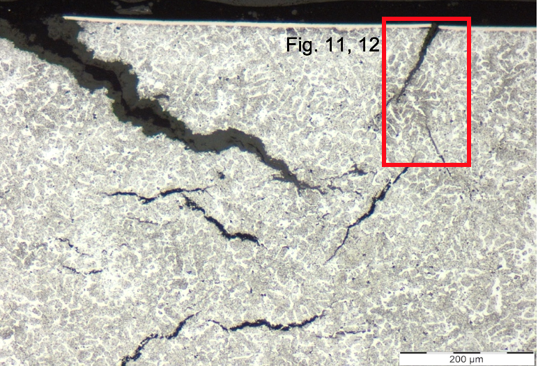
Fig. 9: Micrograph of the metal sample from Fig. 4 (detail), unetched, bright field. The dendrites appear light to dark grey while the interdendritic phase appears white. The metal is characterized by surface cracks as well as internal cracks. The upper red square corresponds to the area selected for elementary mapping by SEM-EDS (Figs. 11 and 12),
 Credit HEI Arc, C.Csefalvay.
Fig. 10: SEM-image in BSE-mode (left) and EDS-spectrum (right), showing the appearance and the chemical composition of the Pb inclusions (red arrrows). The inclusions appear white, the dendrites appear dark grey/black and the interdentritic phase appears grey. Grey opaque patches (yellow arrows) are Fe- and Al-rich phases,
Dendritic structure
Zn
Cu, Sn, Pb, Al
The dendritic phase is heavily oxidized compared to the interdendritic phase (Table 2 and Fig. 12). The corrosion has developed throughout the entire metal body, generating cracks (Fig. 9). The cracks are Zn and O-rich (Fig. 12) and could be composed of zinc carbonate. It could be a case of zinc pest, an intergranular corrosion phenomenon known to cause disintegration in poor quality alloys (Selwyn 2004:155-156, Zhang 2011:890).
The external corrosion products and deposits (Fig. 3) were documented but not analyzed as they were considered to be mainly exogenous in origin and not the main reason behind the deterioration of the object. The orange deposit (S1) is probably soil from Fe-rich environment, while the thin green layer (CP1) is most likely consisting of an oxide of Ni from the metal plating (M1). The white corrosion product (CP2) can either be a salt from the environment, or corrosion products of Zn/Al.
Internal cracking
zinc pest
Nothing to report.
Nothing to report.
 Credit UiO-IAKH, M.Hovind.
The domed, threated fitting consists of a Zn/Al/Pb/Cu/Sn alloy with a Ni-based plating. It has a dendritic microstructure, indicative of production by casting (probably a die cast). The deterioration of the metal could be due to absence of cohesion between the different phases which enabled the penetration of oxygen during the manufacture of the alloy and the formation of internal corrosion products, eventually leading to expansion of its internal structure (zinc pest).
References sample:
1. Selwyn, L. (2004). Metals and corrosion: A handbook for the conservation professional. Ottawa: Canadian Conservation Institute.
2. Zhang, X. G. (2011) “Zinc”. In. Revie R. W. ed. Uhlig’s Corrosion Handbook, 3rd ed. Toronto, ON: John Wiley & Sons, p. 879 – 892.