Coated lamp post(?) fragment
Christian. Degrigny (HE-Arc CR, Neuchâtel, Neuchâtel, Switzerland) & Mathea. Hovind (University of Oslo, Department of archaeology, conservation and history (IAKH-UiO), Oslo, Oslo, Norway)
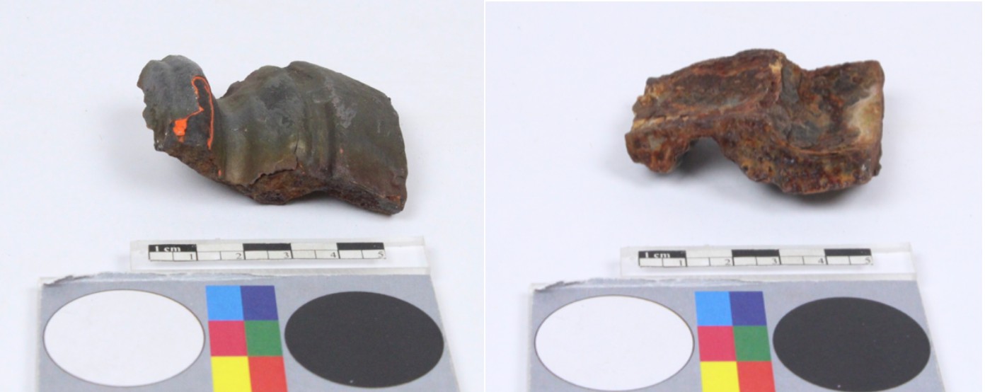
Cast iron fragment, externally coated by alternating layers of bright orange and grey paint (Fig. 1). The piece was found on the street in Zurich, Switzerland and is possibly originating from an outdoor construction (e.g. a lamp post). Dimensions: L = 55mm; W = 50mm; T = 7-10mm; WT = 133g.
Architectural element
Urban area, Zürich, Zurich, Switzerland
Unknown
Modern Times
19th - 20th century
Outdoor atmosphere
Haute Ecole Arc Conservation-Restauration
Haute Ecole Arc Conservation-Restauration
No inventory number.
No recorded conservation data.
Nothing to report.
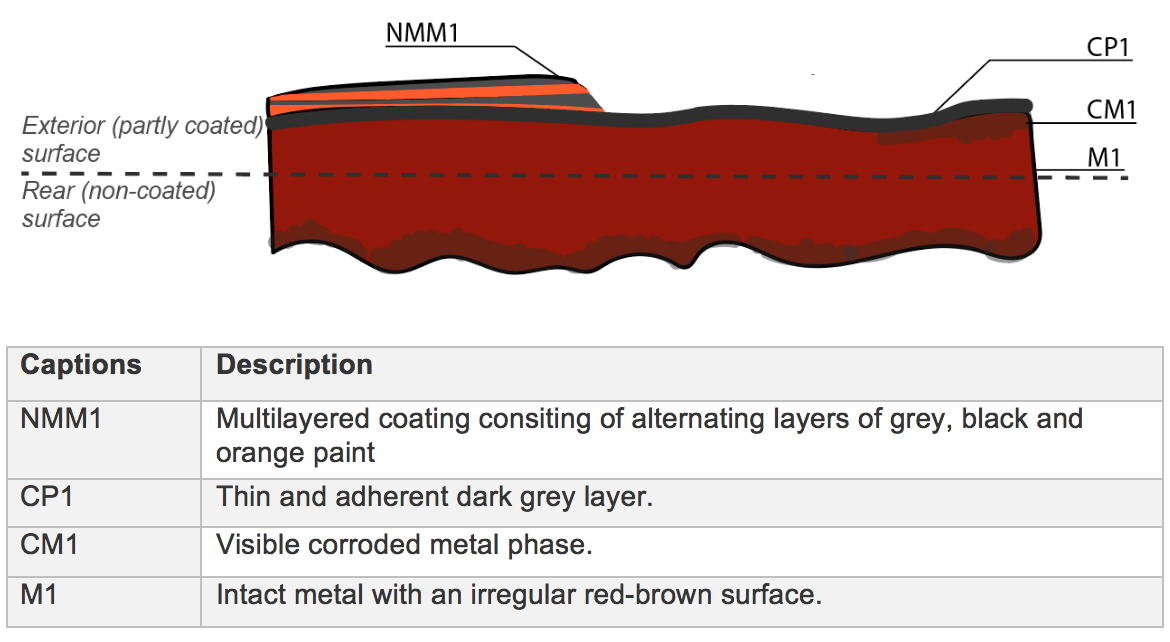
The schematic representation below (Fig. 3) gives an overview of the corrosion layers encountered by visual macroscopic observation.
 Credit UiO-IAKH, M.Hovind.
The sample (Fig. 4) was cut out from one of the profiles of the coated cast iron fragment (Fig. 2). Its vertical surface corresponds to the rear (non-painted) surface, while the top surface contains three layers of paint. The lower surface is where the sample was cut.
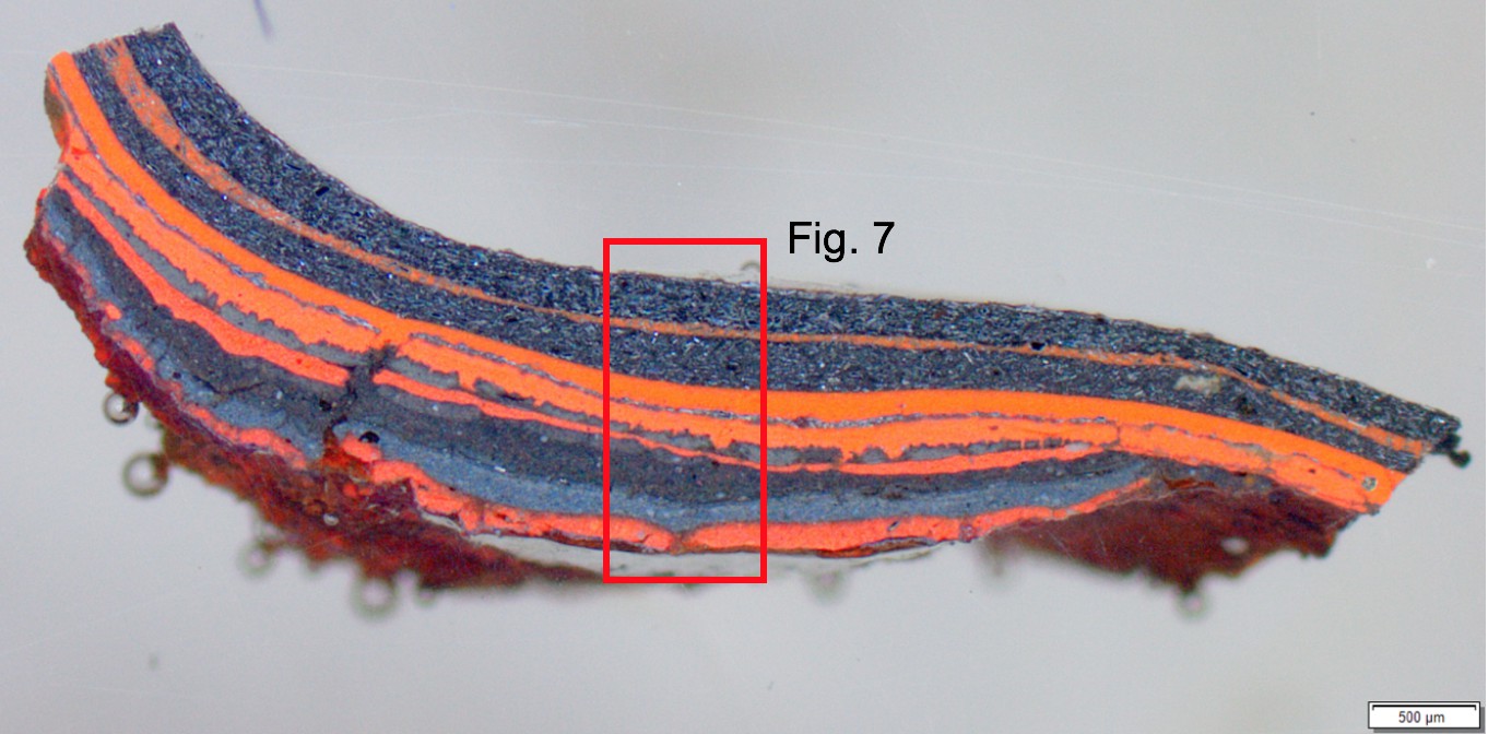
The paint flake (Fig. 5) corresponds to the coating that covers the entire fragment. Its location in relation to the remaining artefact is not known, it is however considered to be representative of the overall surface of the object.
Grey cast iron
As-cast
CCI2018 (Coated Cast Iron) and CCIP2018 (Coated Cast Iron Paint flake)
Haute Ecole Arc Conservation-Restauration
Haute Ecole Arc Conservation-Restauration
March 2018, study of corrosion stratigraphy and elementary analyses
The fact that the fragment was considered a test material enabled extensive sampling that would not otherwise be possible.
Metallography
Microscope: Leica DMi8 (a metallographic, inverted, reflected light microscope) with magnification up to 500X. Camera: Olympus SC50 connected to the software “Olympus Stream”, version 1.9.4. Illumination modes: bright field and cross-polarized light.
SEM-EDS
Instrument: Jeol 6400; voltage: 20 kV; working distance: 18 and 24mm; sample preparation: palladium depot.
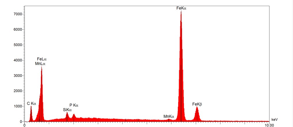
The metal is a grey cast iron with characteristic graphite flakes (Fig. 8). It contains C in addition to P, Mn and some Si (Fig. 9). Its matrix consists of a P-rich eutectoid and a dendritic phase; the latter containing a significant amount of C, but less P than the aforementioned eutectoid (Table 1).
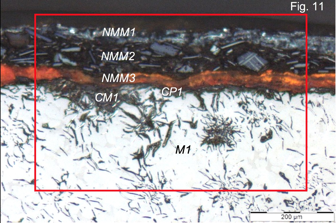
The metal is covered by a coating of alternating layers of paint (appearing light grey, black and bright orange under polarized light, NMM1-NMM3 in Fig. 10). Punctual analyses by SEM-EDS (Table 2) as well as elemental mapping (Fig. 12) reveal that the light grey layer (NMM1) contains a considerable amount of Ba in addition to S, Si and Al. The black layer (NMM2) contains Fe, Si, Mg and Al. The latter is visible as rectangular flakes (see NMM2 in Fig. 11). This layer could consist of Al flakes and FeO in an organic binder (C and O). The underlying, bright orange layer (NMM3) contains Fe and O in addition to a considerable amount of Pb, some Si, Zn and Ca. This layer is probably a preparatory paint consisting of red lead (Pb3O4) and Zn oxide (ZnO). C and O were detected in all layers and are probably components of the binder (Table 2 and Fig. 12).
Furthermore, punctual analyses were carried out in order to determine the chemical composition of the paint flake. Three punctual analyses were carried out for each colour (light grey, black and orange in Fig. 5). The colours correspond to the paint layers previously mentioned, but their composition is slightly different (Table 2, Table 3):
- The light grey layer (similar to NMM1) contains Pb, C and O. Its composition is significally different from NMM1 as it contains neither Ba, S or Al.
- The black layer has a similar composition to NMM2 (C, Fe, O and Al).
- The orange layer is even more rich in lead than NMM3 and contains Ba. This layer is probably a preparatory layer of red lead (Pb3O).
|
Elements mass% |
Fe |
P |
C |
Mn |
Si |
V |
Ca |
S |
Mg |
O |
|
Eutectoid phase |
83 |
10 |
5 |
0.7 |
0.6 |
0.1 |
0.1 |
0.1 |
0.1 |
- |
|
Dendritic phase |
93 |
0.4 |
4 |
0.3 |
2 |
0.1 |
0.1 |
0.1 |
- |
- |
Table 1: Chemical composition of the metal. Method of analysis: SEM-EDS. Lab. of Electronic Microscopy and Microanalysis, Néode, HEI Arc, credit MiCorr_HEI Arc, C.Csefalvay.
|
Elements mass% |
C |
O |
Fe |
Ba |
Pb |
Si |
Al |
S |
Zn |
Ca |
Mg |
Na |
Cl |
P |
Mn |
K |
Ti |
|
NMM1 Light grey |
42 |
23 |
0.6 |
22 |
- |
4 |
4 |
5 |
0.1 |
0.1 |
0.5 |
- |
- |
- |
- |
- |
- |
|
NMM2 Black |
48 |
26 |
18 |
0.4 |
- |
2.1 |
2 |
0.2 |
0.1 |
0.3 |
1.2 |
0.3 |
0.2 |
0.1 |
- |
0.1 |
0.1 |
|
NMM3 Orange |
21 |
26 |
27 |
0.3 |
17 |
2 |
0.8 |
- |
2 |
2 |
0.2 |
0.9 |
0.6 |
0.4 |
0.2 |
0.1 |
- |
Table 2: Chemical composition of the paint layers attached to the metal sample (Fig. 4). Method of analysis: SEM-EDS. Lab. of Electronic Microscopy and Microanalysis, Néode, HEI Arc, credit MiCorr_HEI Arc, C.Csefalvay.
|
Elements mass% |
C |
O |
Fe |
Ba |
Pb |
Al |
Si |
Zn |
Mg |
Na |
P |
Ca |
S |
Mn |
Cl |
K |
Ti |
|
Light grey layer |
22 |
13 |
0.2 |
1.0 |
63 |
- |
0.4 |
0.9 |
- |
0.2 |
0.1 |
0.1 |
- |
0.1 |
- |
- |
- |
|
Black layer |
49 |
29 |
15 |
0.2 |
- |
3 |
2 |
0.1 |
1 |
0.2 |
0.1 |
0.3 |
0.2 |
- |
0.1 |
0.1 |
- |
|
Orange layer |
26 |
17 |
0.1 |
13 |
42 |
- |
0.5 |
0.6 |
- |
0.2 |
0.4 |
0.2 |
|
- |
- |
- |
- |
Table 3: Chemical composition of the paint layers from the paint sample (Fig. 5). Method of analysis: SEM-EDS. Lab. of Electronic Microscopy and Microanalysis, Néode, HEI Arc, credit MiCorr_HEI Arc, C.Csefalvay.
 Credit UiO-IAKH, M.Hovind.
Fig. 8: Micrograph of the metal sample from Fig. 4 (detail), unetched, bright field. The microstructure of the metal consists of graphite flakes in a matrix of dendrites (light grey) and an interdendritic eutectoid phase (light brown). The global analysis of the metal (Fig. 9) was carried out on a surface area of similar size,
 Credit HEI Arc, C.Csefalvay.
 Credit UiO-IAKH, M.Hovind.
Fig. 10: Micrograph of the coated surface on the metal sample from Fig. 4 (detail), unetched, polarized light, showing the colours of the paint layers: NMM3 in bright orange, NMM2 in black with Al flakes in light grey. The uppermost layer, NMM1, appears light grey. The red square corresponds to the area chosen for SEM-imaging in BSE-mode (Fig. 11). The metal appears light grey/white due to movement of the polarizer,
Dendritic structure with graphite flakes and a P-rich eutectic phase
Fe
C, Si, P, Mn
Nothing to report.
The metal is covered by a thin graphitized layer (CP1) as well as a corroded metal phase (CM1). The latter is located just beneath NMM3 and appears dark grey under polarized light (Fig. 10). It consists mainly of Fe and O with Pb and Ca (Table 4, Fig. 12). Pb can probably be explained by the proximity to the Pb-rich paint layer NMM3 (Table 2). The presence of Ca is more interesting however, as it might originate from past exposure to the environment, implying that the paint was not applied immediately after fabrication. The composition of CP1 was not analyzed.
|
Elements mass% |
Fe |
O |
C |
Pb |
Si |
P |
Ca |
Na |
Mn |
Cl |
Mg |
Zn |
K |
Al |
Ba |
|
CM1 |
42 |
32 |
8 |
6 |
4 |
2 |
2 |
1 |
0.9 |
0.7 |
0.5 |
0.5 |
0.4 |
0.3 |
0.3 |
Table 4: Chemical composition of the corroded metal phase (CM1) from Fig. 10. Method of analysis: SEM-EDS. Lab. of Electronic Microscopy and Microanalysis, Néode, HEI Arc, credit MiCorr, HEI Arc_C.Csefalvay.
Multiform
Mostly type II with locally type I (Robbiola)
 Credit UiO-IAKH, M.Hovind.
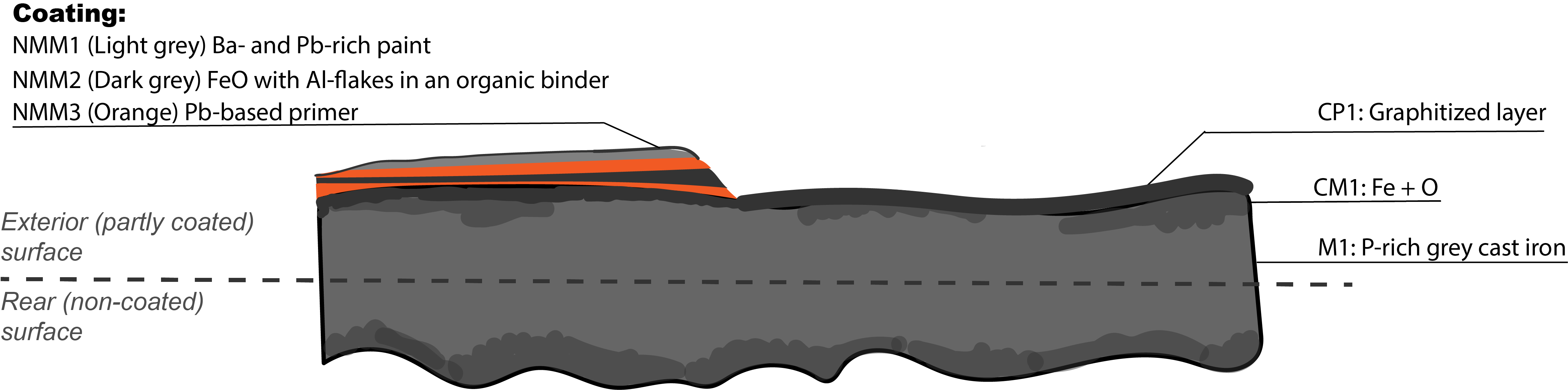
Fig. 13: Corrected stratigraphic representation with results from analyses by SEM-EDS and visual microscopic observation. The colour of the metal was changed to grey as this was the colour of the metal when viewed in cross-section. NMM = non-metallic material, CP = corrosion product, CM = corroded metal, M = metal,
The rain gutter fragment is a grey cast iron with a microstructure consisting of graphite flakes and a P-rich eutectic phase. It is coated by several layers of paint, up to 12 in total. What appears to be a Pb-based primer is located right next to the metal, followed by a black layer consisting of aluminium flakes and iron oxide in an organic binder and superimposed by a light grey, Ba- and Pb-rich paint layer. Inhibitive primers often contain red lead in linseed oil (Hare 2011:979). The uppermost layer is dark in colour and corresponds to the black paint layer previously mentioned.
It seems likely that the rain gutter fragment has been treated with a system of at least three different paints which have all been applied several times, hence the relatively thick coating. The efficiency of the paint system is proven by the fact that internal corrosion is much more prominent in areas that are not protected by paint system. Corrosion control by application of paint films is a well-known treatment of metals (Hare 2011:971, Selwyn 2004:109). The use of an anti-corrosion system consisting of several layers of paint with different colours is known to facilitate monitoring as a break in the coating will be readily visible. Additionally, the presence of more than one paint layer will minimize the risk for a hole in the coating and help avoid localized corrosion (Selwyn 2004:105).
References sample:
1. Selwyn, L. (2004). Metals and corrosion: A handbook for the conservation professional. Ottawa: Canadian Conservation Institute.
2. Hare, C. H. (2011) “Corrosion control of steel by organic coatings”. In. Revie R. W. ed. Uhlig’s Corrosion Handbook, 3rd ed. Toronto, ON: John Wiley & Sons, p. 971 – 983.