Bugatti 37 cylinder head gasket 0416
Christian. Degrigny (HE-Arc CR, Neuchâtel, Neuchâtel, Switzerland) & Elodie. Granget (HE-Arc CR, Neuchâtel, Neuchâtel, Switzerland) & Brice. Chalançon (MNAM (Musée National de l'Automobile de Mulhouse), Mulhouse, Alsace, France)
 Credit He-Arc CR, E.Granget.
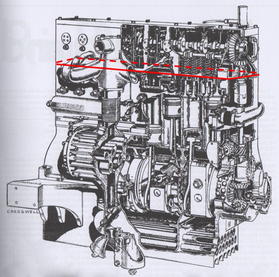
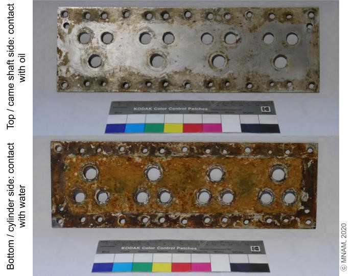
A coolant flows through the cylinder block inside galleries. This aluminium gasket is making a tight junction between the camshaft and the top of the block (Fig. 2). It keeps the water or coolant (water + glycol-based antifreeze) from mixing with the lubricant used on the shaft, the pistons and the cylinders. The wet side is facing the cylinder block. The other side is dry.
Technical object
MNAM (Musée National de l'Automobile de Mulhouse), Mulhouse, Alsace, France
Unknown
Modern Times
The production of this model started in 1926
Outdoor to indoor atmosphere
MNAM (Musée National de l'Automobile de Mulhouse), Mulhouse, Alsace
MNAM (Musée National de l'Automobile de Mulhouse), Mulhouse, Alsace
0416
Vehicule kept functional until 2008 - dismantlement in 2018
A combustion engine transforms thermal energy into kinetic energy. In the Bugatti Type 37, this engine has 3 parts:
- The camshaft case above, where the camshaft coordinates the pistons.
- The cylinder block in the middle, where the cylinders slide in a linear motion.
- The crankcase block below, where the crankshaft transforms the motion from linear to rotative.
The explosion and the cylinders movement are generating a lot of heat. Therefore, the block needs to be cooled down. A cooling system circulates water or coolant between the block [hot] and a heat exchanger (or radiator) [cold]. The circulation of the liquid is often supported by a water pomp. The coolant flows through the block inside galleries in order to cool down the cylinders without wetting them. (Poulain, 1995, p.86)
The Bugatti Type 37 will be restored. When the car was dismantled, this gasket was deemed too corroded to be kept. A new part will be put in its place during the restoration. Consequently, this part has been classified as study material, allowing for sampling for metallography.
Fig.3 clearly shows the limit where the gasket is in contact with the cylinder block ([1] edges and circular openings in the center) and where it is in contact with the coolant ([2] center).
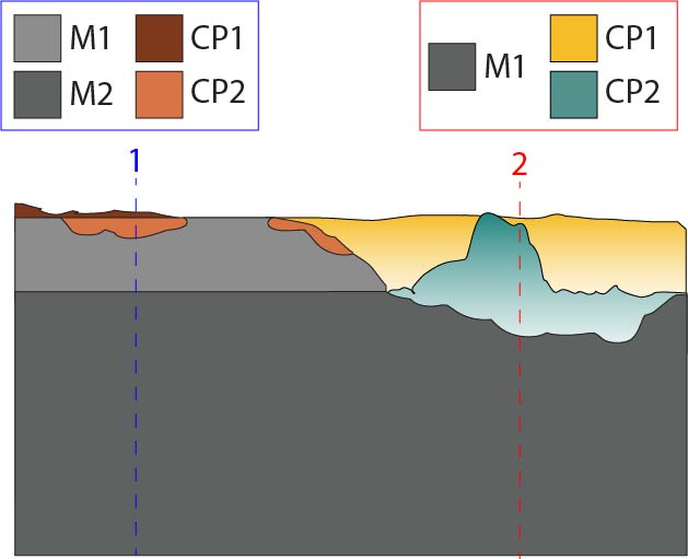
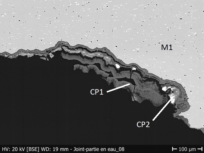
The schematic representation below gives an overview of the corrosion layers encountered on these areas (Fig. 4). The metal core (M1) is colaminated on both sides with metal M2.
| Stratigraphy [1] | Stratigraphy [2] |
| The metal contains the strata M1 and M2. | The first metal stratum is missing and only the core metal (M2 in strat.[1], now M1) remains. |
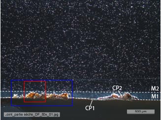
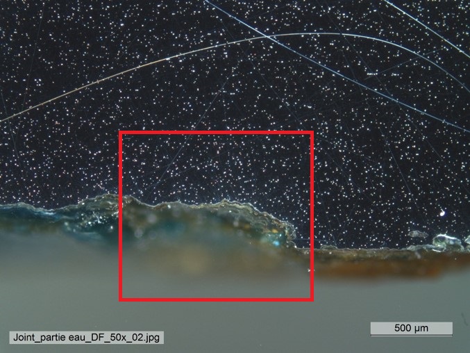
| The CP1 is a thin brown layer loosely attached to the surface of M1. It can be removed with a firm brush. | The CP1 is a thick bright orange layer, really powdery and easily detached. It can be partly removed with a firm brush. The coloration is less important closer to the metal interface, where the products are white. This layer is also really fragile and friable. |
| In some places, CP2 develops within M1. It is colored in bright orange and can be broken in pieces with a toothpick. | The CP2 is peaking through CP1 in some places, colored in green. |
The sample shown on Fig.5 is a transversal cut of the gasket presenting 3 different corrosion sites.
Bottom side:
Contact with coolant [1].
Contact with block [2].
Top side:
Contact with oil (not presented in this artefact sheet).
Al Alloy
Rolled (probably hot rolling) and annealed
None
HE-Arc CR, Neuchâtel, Neuchâtel
MNAM (Musée National de l'Automobile de Mulhouse), Mulhouse, Alsace
31.12.2019 - Sampled for Metallography
During sampling, a large part of the top corrosion layer (CP1) was lost for both zones 1 and 2.
Analyses performed on the gasket:
XRF with portable X-ray fluorescence spectrometer (Niton XL3t 950 Air Goldd+ analyser Thermo Fischer (voltage 50V, General metals mode with acquisition times 20s (main) / 20s (Low) /20s (Light).
Analyses performed on the cross-section sampled from the gasket, on the bottom side (contact with the coolant [1] and with the block [2]):
Metallography (unetched), BF and DF imaging; SEM-EDS (20kV): SE and BSE imaging and semi-quantitative EDS analysis.
None.
This gasket is made out of two metals colaminated: an Al-Cu alloy core (M2 in Fig. 4, Table 1) with on each side a pure Al sheet (M1 in Fig. 4, Table 2).
| Element | mass % |
| Al | 94 |
| Cu | 3.8 |
| Mg | 2 |
| Mn | 0.7 |
| Si | 0.1 |
Table 1: Chemical composition (mass %) of the metal (core) of the gasket. Method of analysis: SEM-EDS, HEI-Arc, S.Ramseyer.
| Element | mass % |
| Al | 99.6 |
| Fe | 0.3 |
| Si | <0.1 |
Table 2: Chemical composition (mass %) of the metal (colaminated protective sheet) of the gasket. Method of analysis: SEM-EDS, HEI-Arc, S.Ramseyer.
Fig. 7 shows oriented inclusions on both M1 and M2, as well as a lot of small pores in M2.
Local analyses on each phase appearing on Fig. 7 showed that the roll-bounded metal M1 is a compact (non-porous) sheet of pure Al (Table 1) with oriented inclusions of Fe and Si. The core M2 is a very porous alloy composed of Al with bigger oriented inclusions of Si, Mn, Fe, Mg.
 Credit HEI Arc, S.Ramseyer / Edit: He-Arc CR, E.Granget.
 Credit HEI Arc, S.Ramseyer / Edit: He-Arc CR, E.Granget.
Fig 7: SEM detail (BSE mode) of zone 1 of the colaminated sheet in cross-section. The core metal (M2) is porous (in black) and shows oriented inclusions (in white) and the colaminated metal (M1) is compact and has smaller oriented inclusions (in white). Corrosion products (in dark grey) are limited to M1,
Unknown
Al
Mg, Si, Mn, Cu, Fe
None.
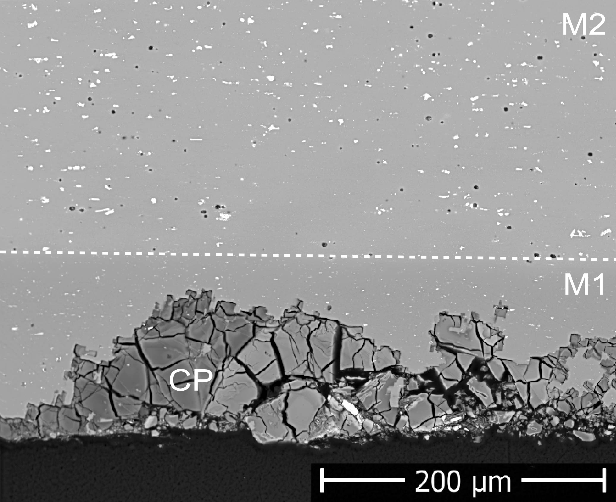
Fig. 7 shows that the corrosion products progress through M1 and develop a network of cracks. Fig. 8 shows that the corrosion can expand even further through M2 (zone 2), the corrosion products being more stratified (Fig. 9).
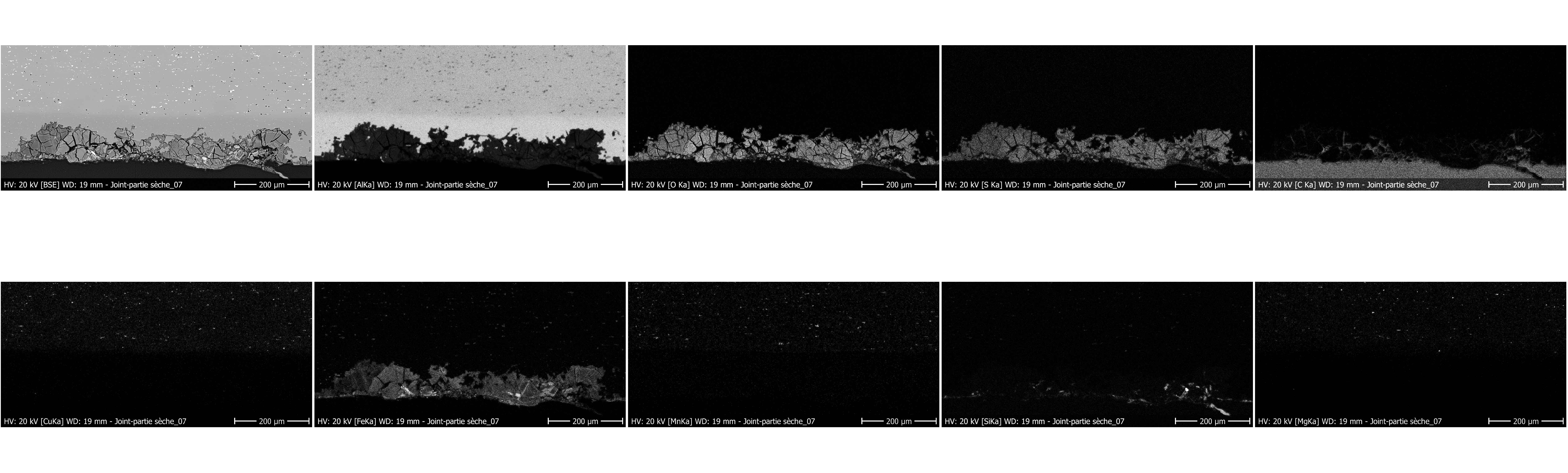
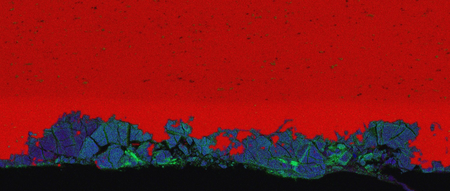
The EDS elemental chemical distribution of zone 1 is given in Fig. 11 to 13. The corrosion layers contain S (probably aluminium sulfate (Fig. 12), polluted with Fe (Fig. 11)). The presence of sulfur can be explained by the proximity of the gasket to the combustion chamber. As for the iron, it is probably coming from the steel block.
 Credit HEI Arc, S.Ramseyer / Edit: He-Arc CR, E.Granget.
 Credit HEI Arc, S.Ramseyer / Edit: He-Arc CR, E.Granget.
Fig 9: SEM detail (BSE mode) of zone 2 of the gasket in cross-section. The colaminated Al is missing. The core metal (now M1) is porous (black spots) and shows oriented inclusions (in white). The corrosion products (CP1) are very friable and retain clusters of inclusions that are also corroded (CP2),
 Credit HEI Arc, S.Ramseyer.
 Credit HEI Arc, S.Ramseyer.
 Credit HEI Arc, S.Ramseyer.
Multiform
?
None.
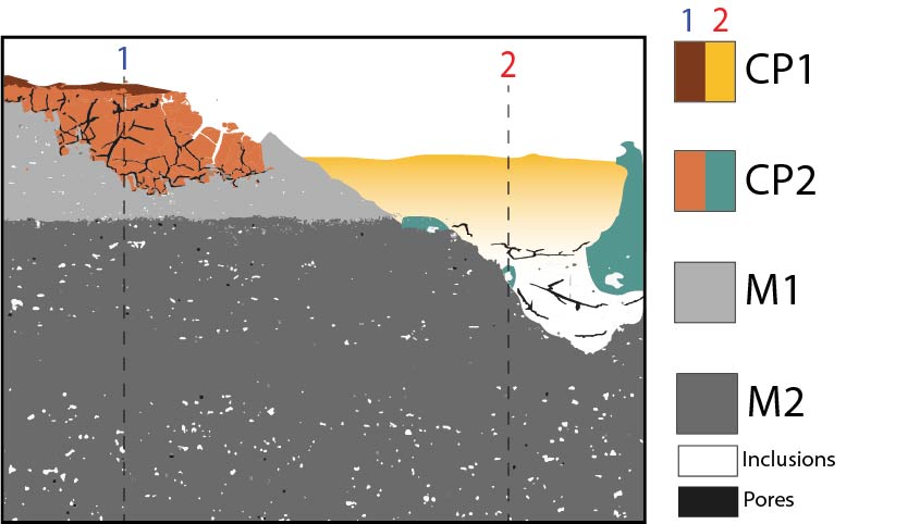
The schematic representations of corrosion layers of Figs. 6 and 7 integrating additional information based on the analyses carried out is given in Fig. 16.
No analyses could be carried out on the top thicker part of CP1.
The cylinder head gasket of this Bugatti Type 37 is made of colaminated aluminium alloys. A pure aluminium sheet (with traces of Fe and Si) protects an Al-Cu core alloy (Al, Cu, Mg, Mn, Si) on both sides of the gasket. The gasket seals the upper part of the cylinder block, preventing coolant from flowing to the camshaft or cylinders.
The side of the gasket facing the cylinder block has a different corrosion pattern depending on whether the area is immersed or not. The surface in contact with the cylinder block shows a priori corrosion consisting of highly cracked aluminium sulphate (network). The surface immersed in the coolant is heavily corroded. The colaminated Al sheet has been completely consumed, and the corrosion progresses through the support metal, retaining inclusions of the alloy in its products. This layer is very brittle and tends to delaminate.
All the corrosion products are contaminated with iron oxides, probably from the block. The immersed part is covered with a thick crust of what is believed to be a mixture of ferrous and aluminium-based products.
References on object and sample
References object
1. Poulain, P. and J-M. (1995) Voitures de collection : Restauration Mécanique Editions Techniques pour l’Automobile et l’Industrie (ETAI), Paris.
2. Granget, E. (2020) La corrosion des alliages d’aluminium des circuits de refroidissement à eau de véhicules en contexte patrimonial : Utilisation d’outils open-access dans l’établissement d’un diagnostic des altérations d’un corpus de véhicules conservés au Musée National de l’Automobile de Mulhouse (Collection Schlumpf), Rapport interne MNAM.
References sample
3. Granget, E. (2020) La corrosion des alliages d’aluminium des circuits de refroidissement à eau de véhicules en contexte patrimonial : Utilisation d’outils open-access dans l’établissement d’un diagnostic des altérations d’un corpus de véhicules conservés au Musée National de l’Automobile de Mulhouse (Collection Schlumpf), Rapport interne MNAM.
References on analytic methods and interpretation
4. Vargel, C. (2004) Corrosion of Aluminium, Elsevier.
5. Degrigny C. and Schröter J. (2019) Aluminium Alloys in Swiss Public Collections: Identification and Development of Diagnostic Tools to Assess Their Condition, in METAL 2019, proceedings of the ICOM-CC Metal WG interim meeting, eds. C. Chemello, L. Brambilla, E. Joseph, Neuchâtel (Switzerland), 408-415.