Sword M-Sch-B2735
Marianne. Senn (Empa, Dübendorf, Zurich, Switzerland) & Christian. Degrigny (HE-Arc CR, Neuchâtel, Neuchâtel, Switzerland)
Sword of the middle la Tène type, broken into two parts (Fig. 1). Under a hand lens the surface shows parallel grinding traces from mechanical cleaning.
Weapon
Marin-Epagnier, La Tène, Saint-Blaise, Neuchâtel, Switzerland
Water finds, end 19th/beginning 20th cent. AD
Iron Age
La Tène C
Soil
Museum Schwab, Biel/Bienne, Bern
Museum Schwab, Biel/Bienne, Bern
M-Sch-B2735
Conserved (not recorded, but mechanical cleaning visible)
None.
None.
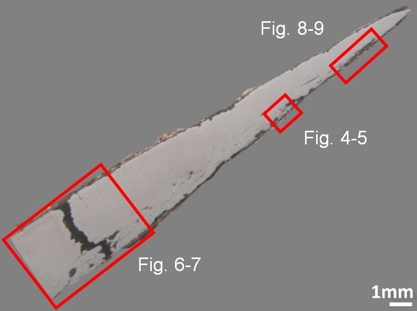
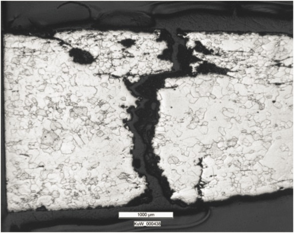
The sample includes half of the sword blade (Figs. 2 and 3). The corrosion layer is thin (Fig. 3).
P-rich iron
Forged, annealed and cold worked
M-SCH-B2735
HE-Arc CR, Neuchâtel, Neuchâtel
Schweizerisches Landesmuseum, Zürich, Zurich
1969, metallography
None.
Analyses performed:
Metallography (nital etched), Vickers hardness testing, LA-ICP-MS, SEM/EDS.
None.
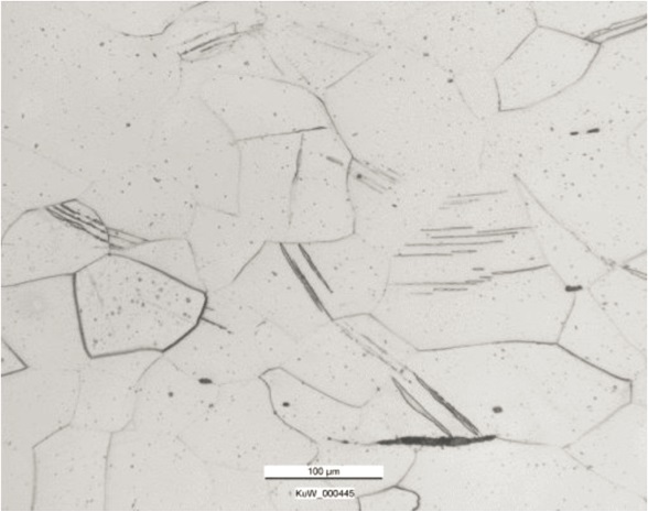
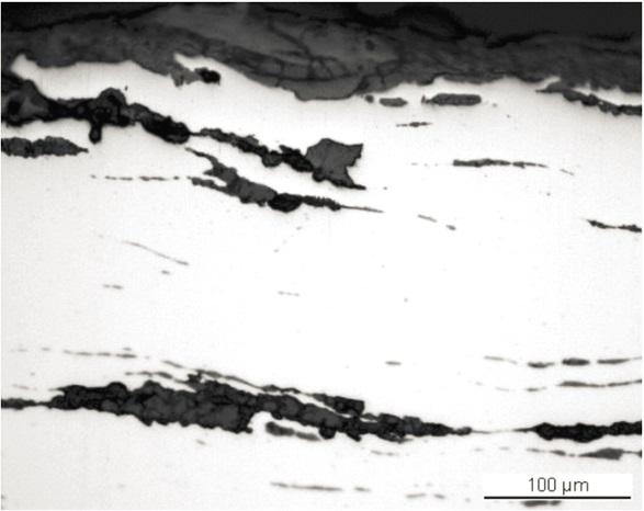
The remaining metal is a P-rich (0.2 mass%) iron (Table 1) with long parallel slag inclusions (Fig. 4) concentrated on one side of the blade. The slag inclusions are composed of wüstite/FeO dendrites and fayalite/Fe2SiO4 in a glassy matrix (Fig. 5 and Table 2). Their chemical composition is typical for iron produced by the bloomery process (dominated by iron oxides and silica). It is difficult to identify the ore type from the slag composition. Interestingly in one case the slag composition is very specific (alumina and P-rich material). After etching, the metal shows a ferritic structure (Fig. 6). The grain size is variable (between ASTM grain sizes of 4 to 7) and some grains include Neumann bands (Fig. 7). A large crack has developed through the metal section (Figs. 3 and 6). The average hardness of the metal (HV1 185) is quite high for a wrought iron. The level of hardness and Neumann bands are typical for a P-rich iron. Neumann bands are said to develop by cold working and shock deformation. According to Swiss and McDonnell 2003 they form when little cold work is carried out. Distortion (grain deformation) after cold working starts to be apparent in iron after a reduction in thickness of between 30-40%. Since no grain deformation is visible, the present reduction is probably a little less than this range.
| Elements | V | Cr | Mn | P | Co | Ni | Cu | As | Ag |
|---|---|---|---|---|---|---|---|---|---|
| Median mg/kg | < | 5 | 10 | 2200 | 140 | 270 | 500 | 260 | < |
| Detection limit mg/kg | 1 | 4 | 1 | 50 | 1 | 1 | 1 | 2 | 0.1 |
| RSD % | - | 56 | 48 | 10 | 14 | 16 | 37 | 15 | - |
Table 1: Chemical composition of the metal. Method of analysis: LA-ICP-MS, Lab Analytical Chemistry, Empa (for details see Devos et al. 2000).
| Structure | MgO | Al2O3 | SiO2 | P2O5 | K2O | CaO | TiO2 | MnO | FeO | Total | SiO2/Al2O3 |
|---|---|---|---|---|---|---|---|---|---|---|---|
| Wüstite in glass | 0.7 | 2.1 | 15 | 2.7 | < | 0.6 | < | < | 87 | 109 | 7.2 |
|
Wüstite and fayalite in glass |
< | 4.8 | 24 | 0.7 | 1 | 1.4 | < | < | 70 | 103 | 5.0 |
|
Wüstite and fayalite in glass |
0.6 | 2.7 | 23 | 1.8 | < | 0.8 | < | < | 69 | 98 | 8.4 |
| Fayalite in glass | < | 5.6 | 26 | 2.8 | 0.8 | 1.4 | < | < | 72 | 110 | 4.8 |
| Fayalite phase | 0.8 | 1.0 | 31 | 1.2 | 0.7 | 1.1 | < | 0.8 | 69 | 106 | 33 |
| Fayalite in glass | < | 8.8 | 24 | 3.2 | 1.0 | 1.4 | 0.6 | < | 66 | 106 | 2.8 |
Table 2: Chemical composition of the slag inclusions (mass%) at the tip (pearlite) and the body (ferrite) of the knife. Method of analysis: SEM/EDS, Laboratory of Analytical Chemistry, Empa.
 Credit HE-Arc CR.
 Credit HE-Arc CR.
 Credit HE-Arc CR.
Recrystallized grains, Newman bands, ghost structure
Fe
P
None.
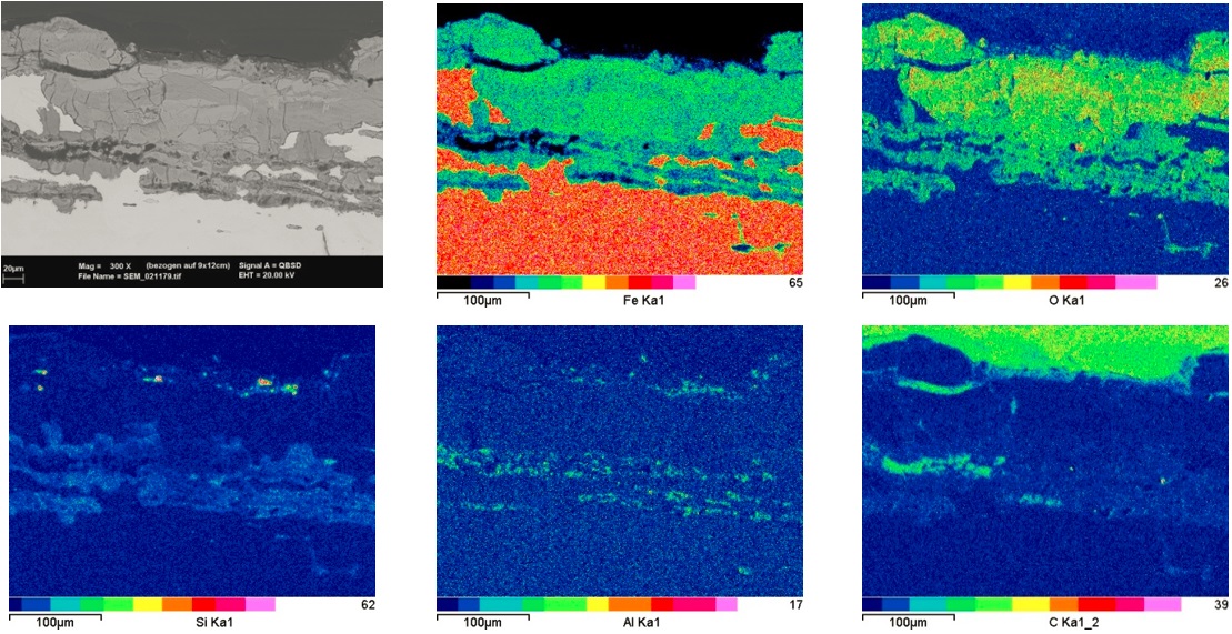
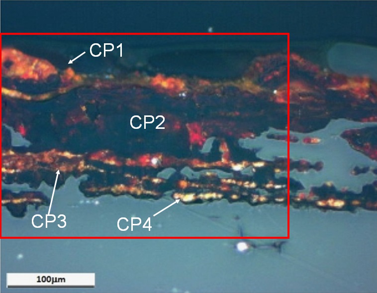
The remaining metal, including the large crack, is covered by a thin, fissured corrosion crust (Figs. 3, 4, 6 and 8). The corrosion crust is thicker on the side containing the long slag inclusions (Fig. 3). In bright field and in the BSE-mode of the SEM image only light and dark-grey areas can be distinguished (Figs. 4 and 9). Under polarised light the corrosion products appear yellow-orange near the metal surface and then become successively dark-red and black. The outer layer (CP1) is orange-yellow, as is the inner one (CP4, Fig. 8). There is a correlation between the level of grey in SEM/BSE-mode, the colours under polarised light, and the chemical composition of the corrosion layer (Table 3, Figs. 8 and 9). The lighter the grey of the SEM/BSE-mode, or the colours (light-brown and red) under polarised light, the richer the area is in Fe and the more depleted it is in O. Surprisingly the inner corrosion layers (CP3 and CP4) are contaminated with Si, Al and O.
|
Elements |
O | Si | Fe | Total |
|---|---|---|---|---|
| Light or dark-red corrosion products (CP3) | 25 | 1.6 | 67 | 94 |
| Light or dark-red corrosion products (CP3) | 32 | < | 74 | 108 |
| Dark or dark-red corrosion products (CP2) | 41 | < | 67 | 109 |
Table 3: Chemical composition (mass %) of the corrosion layer (from Fig. 9). Method of analysis: SEM/EDS, Laboratory of Analytical Chemistry, Empa.
 Credit HE-Arc CR.
Fig. 8: Micrograph showing the metal - corrosion crust interface from Fig. 3 (inverted picture, rotated by 135°, detail) and corresponding to the stratigraphy of Fig. 10, unetched, polarised light. The metal appears in blue and the corrosion changes from yellow-orange (CP4) to dark-red (CP3), black (CP2) and orange (CP1). The area selected for elemental chemical distribution (Fig. 9) is marked by a red rectangle,
Uniform - transgranular
Unknown
None.
None.
The sword blade is made of a hard, P-rich iron. It displays poor workmanship compared to other Celtic swords. The metal was first hot worked followed by a final cold working. The corrosion layer, typical of terrestrial context, has been partially removed by the conservation treatment. The possible use of air abrasive cleaning with glass beads and aluminium oxide, or the use of abrading tools, could explain the enrichment in Si and Al of the surface.
References on object and sample
References object
1. Senn Bischofberger, M. (2005) Das Schmiedehandwerk im nordalpinen Raum von der Eisenzeit bis ins frühe Mittelalter. Internationale Archäologie, Naturwissenschaft und Technologie Bd. 5, (Rahden/Westf.), 30.
References sample
2. Senn Bischofberger, M. (2005) Das Schmiedehandwerk im nordalpinen Raum von der Eisenzeit bis ins frühe Mittelalter. Internationale Archäologie, Naturwissenschaft und Technologie Bd. 5, (Rahden/Westf.), 240-242.
References on analytic methods and interpretation
3. Swiss, A. J. and McDonnell, J.G. (2003) Evidence and interpretation of cold working in ferritic iron. International Conference, Archaeometallurgy in Europe 2003, Proceedings, vol. 1, Milan, 209-217.
4. ASTM E112-13: Standard Test Methods for Determining Average Grain Size.