Knife with a groove on both sides DEV 995 814 PR
Marianne. Senn (EMPA, Dübendorf, Zurich, Switzerland) & Christian. Degrigny (HE-Arc CR, Neuchâtel, Neuchâtel, Switzerland)
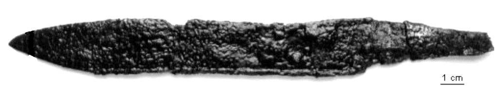
Knife, with a groove on both sides of the blade spine (Fig. 1). Dimensions: L = 20.1cm; WT = 30g.
Household implement
Settlement Develier, Courtételle, Jura, Switzerland
Excavated in 1995, farm 1
Early medieval times
Soil
Office de la Culture, Porrentruy, Jura
Office de la Culture, Porrentruy, Jura
DEV 995/814 PR
Conserved between 1995 and 2000: desiccation below 80°C, mechanical cleaning, passivation with tannic acid and protection with Paraloid B72® (Eschenlohr et al. 2007, 75).
None.
None.
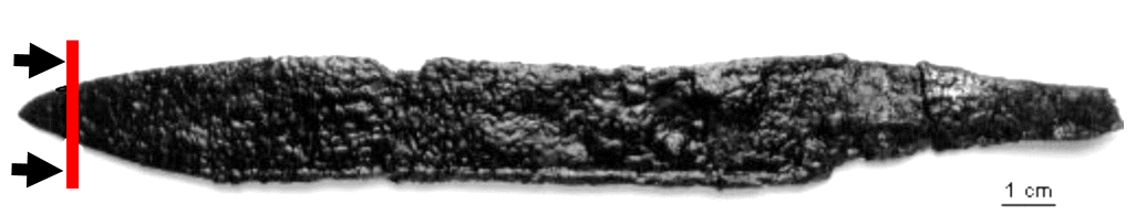
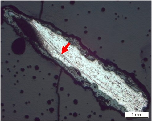
The cross-section shows a cut through the tip of the knife (Fig. 2). The metal is surrounded by thick corrosion products (Fig. 3). Dimensions: L = 8mm; Wmax. = 2mm.
Fe Alloy
Hot worked, composite of two wrought iron bars, tip cemented, quench-hardened and tempered
DEV 814
HE-Arc CR, Neuchâtel, Neuchâtel
Office de la Culture, Porrentruy, Jura
2000, metallography and chemical composition of the metal
None.
Analyses performed:
Metallography (nital etched after etching with Oberhoffer’s reagent), Vickers hardness testing, LA-ICP-MS, SEM/EDS.
None.
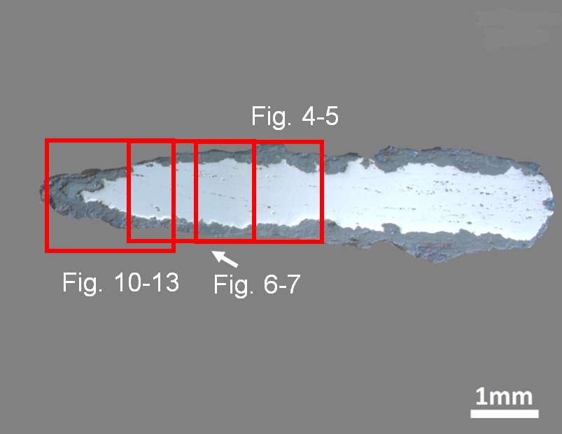
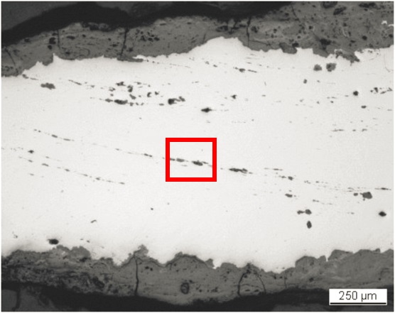
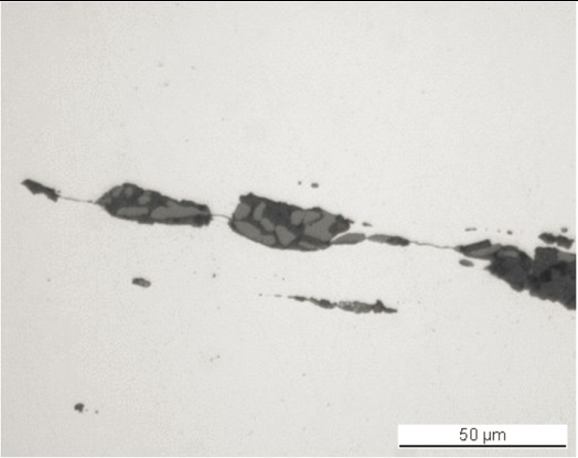
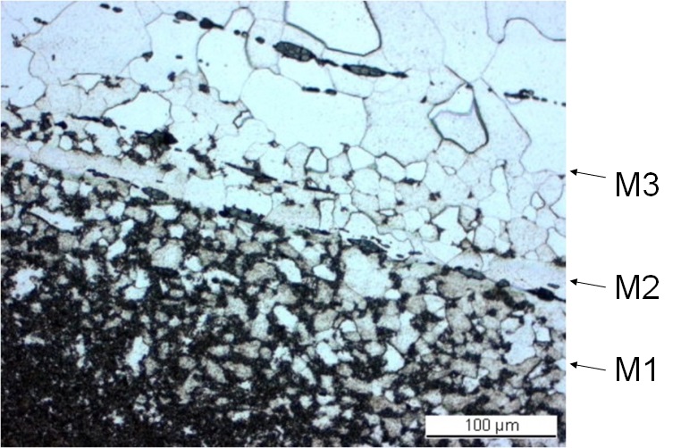
The remaining metal consists of two forged wrought iron bars, one of which includes a carburized tip (M1, Table 1). They are separated by a welding seam (M2, Figs. 8 and 9). The ferritic part (M3) is Cu-rich, whereas the carburized tip has a low and medium content of trace elements (Table 1). The metal contains elongated slag inclusions (Fig. 4) showing a structure of wüstite (FeO) in a glassy matrix (Fig. 5 and Table 2). Most of the slag inclusions are arranged in rows, marking the welding seam (Figs. 4 and 8) and following the forging direction. Their chemical composition differs in the Mn content (Table 2): the latter is higher in the slag inclusions of the carburized tip. The high P content of the slag in the ferritic part must be noted since the metal in general has a medium P content (Tables 1 and 2). Etching with Oberhoffer’s reagent solution makes the P distribution visible (Fig. 9). Dark areas are depleted of P whereas P-rich zones, such as those found in the welding seam, appear in white. After nital etching, the very fine steel microstructure of the tip shows the transition from hypoeutectoid to eutectoid steel (ferrite component in white and pearlite component in black, partly bainite, Figs. 6, 7 and 8). The body of the knife is made of wrought iron with an annealed, irregular ferritic structure (Figs. 6 and 7). The average hardness of the wrought iron (HV1 130) is a little higher than expected, whereas the hardness of steel in the hypoeutectoid-eutectoid tip (HV1 360) is an indication of quench-hardening followed by tempering.
| Elements | V | Cr | Mn | P | Co | Ni | Cu | As | Ag | Ni/Co | C* mass% |
|---|---|---|---|---|---|---|---|---|---|---|---|
| Body M3 (median of 2 similar analyses) mg/kg | < | < | 7 | 400 | 60 | 20 | 1300 | 300 | < | 0.3 | 0/0.2 |
| Tip - M1 (median of 7 similar analyses) mg/kg | < | 4 | 100 | 500 | 40 | 70 | 400 | 70 | < | 1.8 | 0.8 |
| Detection limit mg/kg | 0.7 | 2 | 0.4 | 68 | 0.4 | 3 | 2 | 0.8 | 0.4 | ||
| RSD1 % | - | 26 | 95 | 92 | 9 | 3 | 79 | 24 | |||
| RSD2 % | - | - | 112 | 42 | 13 | 26 | 20 | 47 |
*visually estimated
Table 1: Chemical composition of the metal. Method of analysis: LA-ICP-MS, Laboratory of Analytical Chemistry, Empa (for details see Devos et al. 2000).
| Structure | Location | Na2O | MgO | Al2O3 | SiO2 | P2O5 | K2O | CaO | TiO2 | MnO | FeO | Total | SiO2/Al2O3 |
|---|---|---|---|---|---|---|---|---|---|---|---|---|---|
| Glass | Pearlite, tip | 0.7 | < | 9.8 | 72 | < | 6.2 | 3.3 | 0.9 | 1.7 | 8.9 | 104 | 7.3 |
| n. d. | Pearlite, tip | < | < | 3.5 | 34 | < | 1.5 | 1.1 | < | 1.0 | 65 | 107 | 9.8 |
| n. d. | Ferrite (average of 4 similar analyses), body | < | 0.9 | 3.8 | 30 | 1.2 | 1.5 | 1.6 | < | < | 64 | 104 | 7.8 |
| n. d. | Ferrite, body | < | < | 1.5 | 14 | < | 0.7 | 0.6 | < | < | 88 | 105 | 9.3 |
n. d. = structure not determined
Table 2: Chemical composition of the slag inclusions (mass%) at the tip (pearlite) and the body (ferrite) of the knife. Method of analysis: SEM/EDS, Laboratory of Analytical Chemistry, Empa.
 Credit HE-Arc CR.
 Credit HE-Arc CR.
 Credit HE-Arc CR.
 Credit HE-Arc CR.
 Credit HE-Arc CR.
Recrystallized grain structure
Fe
C, Cu
None.
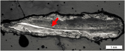
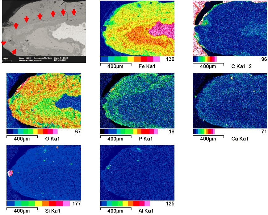
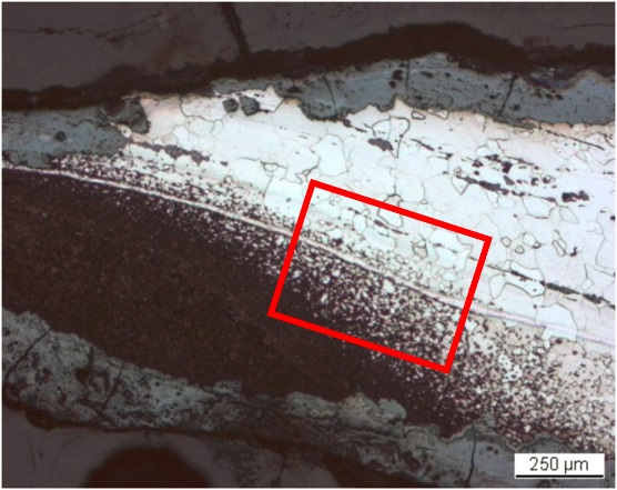
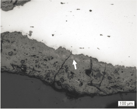
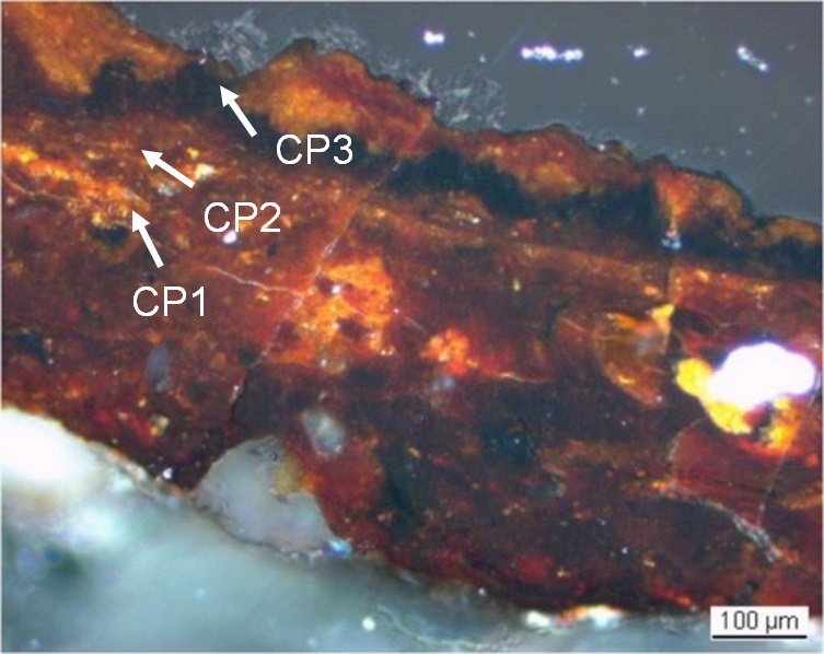
The metal - corrosion products interface is irregular (Figs. 3, 4 and 10) and the average thickness of the corrosion crust is 200µm. In bright field, the corrosion appears grey, rather heterogeneous and heavily cracked. A thin light-grey layer (indicated by an arrow in Fig. 10) can be detected. Under polarised light the corrosion is more clearly stratified, the thin layer mentioned before is black (CP3) and surrounded by dark-brown (CP2) and orange-red (CP1) corrosion layers (Figs. 11 and 12). It contains less O (magnetite or hematite?) than the orange-brown corrosion products (iron hydroxides?) (Table 3 and Fig. 13). The outer corrosion layer (covering the aforementioned thin black layer) contains external markers such as quartz grains and other rock fragments (Ca, Fig. 13). The shape of the blade is preserved in the corrosion crust (Fig. 13, arrows on the SEM image). The absence of P, an external marker, highlights where the limit of the original surface was located (interface CP1 / CP2).
|
Elements |
O | Si | P | Ca | Fe | Total |
|---|---|---|---|---|---|---|
| Black layer (CP3) | 26 | < | < | < | 69 | 95 |
| Dark-brown corrosion products (average of 3 similar analyses) (CP2) | 29 | < | < | < | 63 | 92 |
| Red / orange corrosion products (CP1) | 32 | 1.4 | 1.1 | 0.7 | 56 | 92 |
Table 3: Chemical composition (mass %) of the corrosion layer (from Fig. 12). Method of analysis: SEM/EDS, Laboratory of Analytical Chemistry, Empa.
 Credit HE-Arc CR.
 Credit HE-Arc CR.
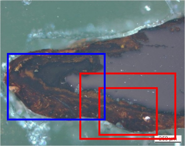
Fig. 11: Micrograph showing the metal - corrosion crust interface from Fig. 3 (detail) unetched, polarised light. The micrographs of Fig. 10 and Fig. 12 are marked by the large and small red rectangles respectively while the area selected for elemental chemical distribution (Fig. 13) is marked by the blue rectangle. The light-grey layer of Fig. 10 (arrow) appears black whereas the rest of the corrosion layer is brown, red and orange,
 Credit HE-Arc CR.
Uniform - transgranular
Unknown
None.
None.
The knife is forged from two wrought iron bars which have been welded together. The tip is carburized. The recrystallized structure of the ferrite is probably the consequence of tempering the tip. The metal compositions of both alloys differ from the one worked in the forges of Develier-Courtételle (Eschenlohr et al. 2007, 71). For this reason this well worked knife is identified as an importation to the early medieval village Develier-Courtételle. The limit of the original surface (limitos) is still preserved in part of the corrosion layers still in place. Chemically it can be located at the interface of the P-rich outer corrosion layer and the P-poor inner corrosion products. Visually it can be located by the presence of sediments in the outer corrosion layers and most likely by the hardness and coloration of the inner corrosion products (magnetite?). It is an example of a terrestrial corrosion crust.
References on object and sample
References object
1. Eschenlohr, L., Friedli, V., Robert-Charrue Linder, C., Senn, M. (2007) Develier-Courtételle. Un habitat mérovingien. Métallurgie du fer et mobilier métallique. Cahier d'archéologie jurassienne 14 (Porrentruy), 302.
References sample
2. Eschenlohr, L., Friedli, V., Robert-Charrue Linder, C., Senn, M. (2007) Develier-Courtételle. Un habitat mérovingien. Métallurgie du fer et mobilier métallique. Cahier d'archéologie jurassienne 14 (Porrentruy), 266.