Metal objects are subject to corrosion and different methods exist to document it from the less to the most invasive: macroscopically, under binocular microscope and on cross-sections. In order to compare that information into a database, some comparable terms have to be used.
As for the less invasive approaches (macroscopically and under binocular microscope), Bertholon has developed a descriptive methodology (Bertholon, 2000) with precise terms to describe physical properties of corrosion layers on metal objects.
This description method is aimed at conservation professionals as a support to identify the limit of original surface (limitos). This interface is the original form of the object before its abandonment. As for archaeological objects, this concept is highly significant as the form of the object is often lost in its outer corrosion layers. Therefore, it is important to identify outer and inner strata.
The use of the same/similar terms by all users makes it possible to compare data collected and to identify unknown corrosion in order to facilitate the diagnosis on metallic objects.
First of all, a macroscopic observation (with naked eyes) is conducted on the object. Usually, pictures (general (see Fig. 1) and details) and metadata are collected at this point. It is also useful to specify the material history of the object in order to know the environments in which the observed corrosion may have developed (indoor corrosion, archaeological corrosion, previous restoration, etc). All these data accompany the object in its object’s sheet.
The macroscopic observation of the object allows to appreciate the distribution of the different forms of corrosion on the whole surface of the object, as indicated below:
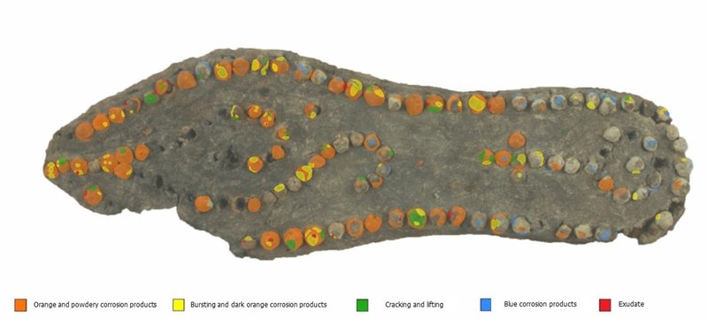
Fig. 1: Location of the corrosion forms observed on the nails of a Roman sole from Avenches site, © HE-Arc CR, L. Pedersen.
The descriptive method by Bertholon is based on the description of “strata” (sediments, deposits, corrosion products, residual metal, etc. see below) which develop on the surface of metal objects. By observing the artefacts surface under a binocular microscope, the conservation professional tries to understand the stratigraphy (succession of strata) of the corrosion forms (Fig. 2). At this stage, it is possible to probe with a scalpel a localized window that is considered sufficiently representative. The characteristics (morphology, texture, etc.) and sub-characteristics (shape, colour, width, compactness, cohesion, etc.) of the strata are assessed sensorially (in contact with the blade) and noted.

Fig. 2: Visual observation of an artefact under a binocular microscope, © HE-Arc CR, R. Jeanneret.
The conservation professional compiles all data collected in a first schematic representation of the corrosion structure(s) observed, which he.she corrects after having examined several other areas of the surface of the object. The graph produced is a conceptual and visual image summarizing the forms of corrosion (stratigraphies of strata) observed on the surface of the object (Fig 3). It should match the macroscopic appreciation of the different corrosion forms. This conceptual approach is the first step in the descriptive methodology of corrosion structures developed by Bertholon.

Fig. 3: Schematic representation of corrosion structures observed on an artefact deduced from visual observation and local probing, © HE-Arc CR, E. Rotzetta.
The second step is the codification of the strata of the corrosion structures. According to Bertholon (2000), a stratum “defines a volume of material presenting a set of characters appearing homogeneous at the scale at which this volume of material is observed. Strata are the result of a virtual and reasoned separation of all constituent materials (including corroded materials) into volumes considered sufficiently homogeneous from the point of view of the characteristics considered. The stratum is the basic descriptive unit of the method.”
Corroded Metal (CM)
A stratum formed of both metal and corrosion products or exhibiting internal corrosion. Typical examples: volume of metal partially transformed by intergranular or interdendritic corrosion.
Corrosion products (CP)
A stratum formed mainly of corrosion products.
Deposit (D)
A stratum formed by chemical precipitation or biological formation on contact with metal or altered material.
Metal (M)
A stratum consisting of uncorroded metal regardless of the base metal and its stratigraphic position.
Non-Metallic Material (NMM)
A stratum consisting of a non-metallic material. This material can be part of the object, be an element of the decoration, etc., or be associated with the object. The material may or may not be altered.
Pseudomorph of Organic Material (POM)
A stratum composed of materials that may be totally inorganic (corrosion products) or partially organic (wood, leather, textiles, etc.). In this case, the alteration process has led to a preservation of the initial form of the organic materials and a partial or total transformation of the organic matter.
Soil (S)
A stratum formed mainly of materials from the environment and not transformed when in contact with metallic materials. Examples: sediments (even poorly adherent), dust, etc.
Structural Void (SV)
A stratum consisting of material in the gaseous state. A type of stratum generally used to describe an open or closed cavity located between the other strata.
The following example is used to illustrate how the different strata are located and identified (see table 1 and fig. 5):
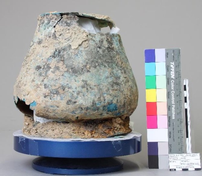
Fig. 4: Situla, inverted as found in situ, La Sarraz, Vaud, Switzerland, © HE-Arc CR, M.-J. Scholl.
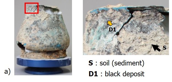
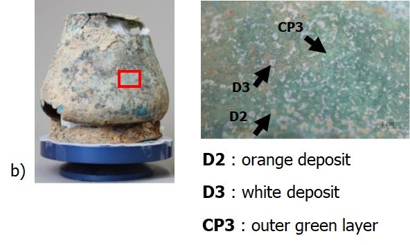
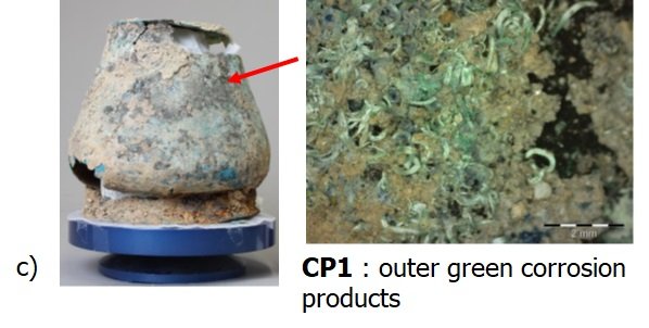
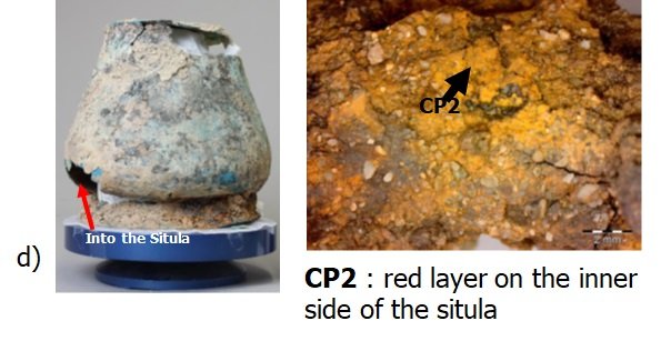
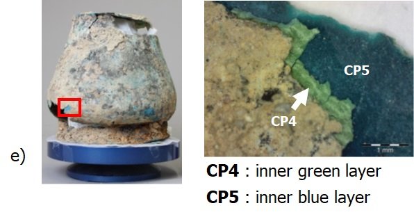
Table 1: Location and identification of strata of the situla of Fig. 4, © HE-Arc CR, M-J. Scholl.
All this information is then summarized in the following schematic representation of corrosion structures (or stratigraphy representation of the corrosion forms observed) of the object.
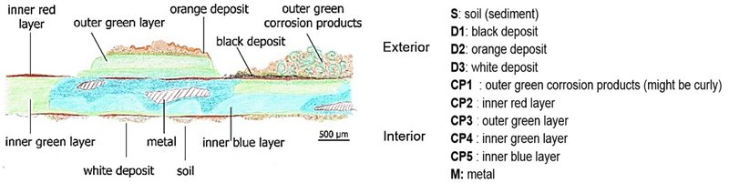
Fig. 5: Schematic representation of corrosion structures observed on the situla of Fig. 4 deduced from visual observation and local probing, © HE-Arc CR, M-J. Scholl.
The third step is the selection of a specific and/or sufficiently representative corrosion structure which will then be represented digitally using the MiCorr “By stratigraphy representation” search engine. In this case three corrosion structures could be considered (see red squares).
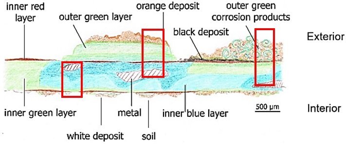
Fig. 6: Selection of representative corrosion structures in the schematic representation of Fig. 5, © HE-Arc CR, M-J. Scholl.
The cross-section is prepared by mounting in resin and polishing of the sample with silicon carbide disks and diamond paste up until ¼ µm. The cross-section sample is then observed under different microscopic techniques. The cross-section observation terminology for the identified “strata” is also adapted from the Bertholon’s method (sediments, deposits, corrosion products, residual metal, etc.). Optical microscopy is used to observe morphological, textural, microstructural and interfacial features of the identified strata. Morphological features such as color, thickness and width can be observed and quantified (width and thickness). Textural features such the presence of inclusions and porosities and the presence of cracking can be identified. Microstructural characteristics (crystalline microstructure, pseudomorph of grain microstructure, presence of alternative bands, etc.) can also sometimes be observed. Interfacial attributes can be perceived such as the profile appearance (irregular, bumpy, straight, etc.), the transition (gradual, sharp, diffuse, etc.) between adjacent strata, adherence and roughness.
The characteristics of the corrosion products can be observed both in bright field and dark field mode, which are differently informative depending on the nature of the object (for example, more information can be obtained for iron alloys corrosion products in bright field mode, while the dark field mode is usually more informative for copper alloys corrosion products).
Optical microscopy in bright field mode allows to observe the metal microstructure after chemical etching. It is possible to observe microstructure features (dendrites, deformed dendrites, equiaxe grains, elongated grains, etc.) and sub-characteristics (slip lines, twin lines, eutectic phases, etc.) as well as it is possible to quantify the presence of porosities and inclusions through image analysis softwares.
Scanning electron microscopy coupled to energy-dispersive X-ray spectroscopy (SEM-EDX) allows to observe chemical contrasts and determine elemental composition (main, secondary and additional elements) for each stratum. Structural characterization techniques such as X-Rays Diffraction (XRD), Raman spectroscopy and Infrared Spectroscopy can be used to determine the compounds composing the corrosion products (goethite, magnetite, malachite, cuprite, etc.).
We explain in the following how to build a digital construction of the stratigraphy of corrosion structures as selected in Fig. 6. The MiCorr “By stratigraphy representation” search engine is accompanying the conservation professional concerned all along the description of a corrosion structure and reminds him.her of the characteristics/sub-characteristics which will eventually be used to compare the structure digitally represented to those of the database.
Digital corrosion structures can be saved online and worked again at any time. All the information added into the system remain private (user's profile).
The conservation professional (named user in the following) clicks on the Search button of the lower menu on the MiCorr homepage. The window below opens (Fig. 7). He.she has then to click on the “By stratigraphy representation” search engine.
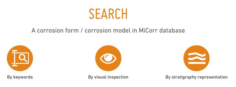
Fig. 7: Screenshot of MiCorr Search tools.
The following window shows-up (Fig. 8) with an indication of the observation mode (binocular or cross-section).
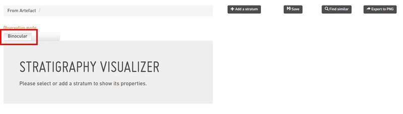
Fig. 8: Screenshot of the first page of the “By stratigraphy representation” search engine, when working in Binocular mode.
Once the mode of observation has been selected, a stratum is added by clicking on “+ Add a stratum” button (Fig. 9). A code with its number is added automatically (when more than one stratum of a type is considered their number progresses from the exterior to the interior of the stratigraphy) and highlighted (with the orange rectangular shape on the left of the stratum) to specify the type of stratum: M (Metal), CM (corroded metal), CP (corrosion product), NMM (non-metallic material), S (soil), D (deposit), SV (structural voids), etc. The fields of the characteristics and sub-characteristics of the strata are provided in parallel. They can be filled once a stratum is created or at the end of the construction of the corrosion strata structure (see below). Each characteristic and sub-characteristic is explained by moving the mouse on its name. Any new stratum added of the corrosion strata structure is appearing below the previous one.
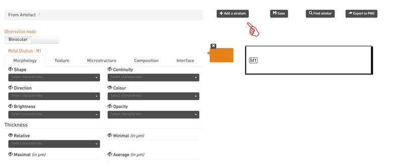
Fig. 9: Screenshot of the Search tool by stratigraphy representation (binocular mode) showing the corrosion strata structure on the right (only “M1” stratum is currently visible) and the characteristics / sub-characteristics of the stratum under investigation on the left.
Once the corrosion strata structure is completed, the user has to re-locate each stratum versus the other using the arrows included next to each code (Fig. 10). When more than one stratum of a type is considered their number progresses from the exterior to the interior of the stratigraphy.
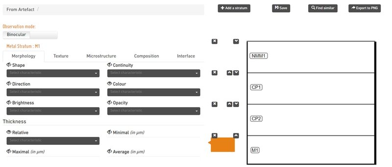
Fig. 10: Screenshot of the Search tool by Stratigraphy representation (binocular mode) showing corrosion strata. The thickness field of each stratum has been filled to visualize correctly the structure (otherwise it would be out of the screen).
CM stratum is an intermediate stratum composed of characteristics from both M and CP (see Fig. 11). The ratio M/CP has to be selected from the composition tab (cross-section mode) and some characteristics do not need to be filled (interface). New sub-characteristics might be added though (microstructures, additional element(s) in M and CP).
CM strata (like M Strata) often needs a cross section sampling in order to be visualised.
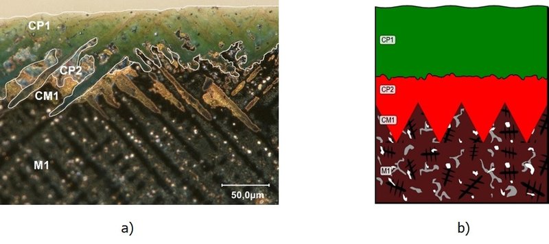
Fig. 11: Metal structure of a copper alloy wristband with a CM1 stratum observed on cross-section, optical microscope, dark field, Archaeological service, Fribourg (a) and MiCorr representatiion of the corrosion structure (b).
The next step is to characterize each stratum. It is an essential step: each field has to be filled to make the comparison with the existing case studies/corrosion forms of MiCorr database more efficient. Sub-characteristic fields should be completed when the information is available (the blank option corresponds to a sub-characteristic which is not known).
For adding the sub-characteristic, select a stratum (it will be highlighted in orange) and start selecting the appropriate term on each dropdown list.
Each term is precisely defined by the Bertholon’s descriptive method. Those term are all presented below, according to the mode of observation (binocular - Bi & cross-section - CS) and further detailed.
The morphology of a stratum is the shape (geometric or not) defined by the volume of the stratum.
Geometry of the stratum. Only the film/coating/layer options are made visible. Certain terms are specific to certain strata. Terms to describe the shape of strata:
Cloud: Continuous or very fine discontinuous outer stratum showing the underlying stratum.
Cluster: Stratum, usually thick, dispersed or isolated, of irregular massive shape.
Crater: Particular shape at the surface of a metal stratum in the form of a cavity that is wider than deep.
Crust: Continuous or discontinuous outer stratum of possibly irregular thickness.
Droplet: Most often outer stratum dispersed or isolated, droplet-shaped stratum.
Film/coating: Thin continuous or discontinuous stratum of regular thickness (on the scale of the observation) and whose faces appear parallel.
Layer: Continuous and discontinuous inner stratum.
Nodule: Generally thick, dispersed or isolated stratum of massive pseudo-geometric shape.
Pit: Particular shape on the surface of a metal stratum in the form of a cavity deeper than wide.
Pustule: Dispersed or isolated stratum of conical or hemispherical shape.
Veins or seams: Continuous or discontinuous stratum.
Whiskers: Stratum in the form of a filament or hair extending over the surface.
The surface orientation represents the direction of the described stratum in relation to the tangential plane of the present surface (or to the mean tangential plane of the present surface in the case of macro-roughnesses or irregularities). Terms to describe the surface orientation of strata:
- Longitudinal
- Oblique
- Transversal
- Multidirectional
Terms to describe the brightness of strata:
Adamantine: Shows a strong diamond like brilliance. Caused by strong refraction of light. Can be observed on corrosion products with a high refractive index and on fairly large crystals (such as cerusite and anglesite, cuprite).
Greasy: Shows a slightly diffuse reflection as if a layer of oil was covering the surface.
Matte: No special reflection, no shine. Caused by a very fine aggregate.
Metallic: Shows high luminance even when the angle of view is varied.
Non-observable brightness
Pearly: Shows surface iridescence. Caused by the refraction of light in crystal layers cleaved parallel to the surface (mother-of-pearl, micas).
Resinous: Resin luster. Some sulphides have a resinous luster
Silky or silklike: Shows a directed reflection of light. Caused by the reflection of light in a fine aggregate of parallel fibrous crystals (some gypsum, malachite).
Submetallic: Shows areas of high luminance and areas of lower luminance even when the viewing angle is varied.
Vitreous: Luster of the glass, like quartz.$
The
continuity of a stratum is assessed in relation to the observed area. Terms to describe the continuity of a stratum in relation to the observed area:
Continuous: Stratum showing no interruption (consisting of a single stratigraphic element) over the observed area
Discontinuous: Stratum with one or more interruption(s) in the observed area
Isolated: Stratum consisting of one or more stratigraphic elements having a minority volume over the area observed
Scattered: Stratum consisting of numerous stratigraphic elements separated from each other and distributed over the observed area
The number of colours offered is deliberately limited in order to allow a reliable transmission of this property in the descriptions. Terms to describe the color of strata:
Yellow: Light/Medium/Dark
Orange: Light/Medium/Dark
Brown: Light/Medium/Dark
Red: Light/Medium/Dark
Pink: Light/Medium/Dark
Magenta: Light/Medium/Dark
Blue: Light/Medium/Dark
Turquoise: Light/Medium/Dark
Green: Light/Medium/Dark
Grey: White/Extra light/Light/Medium/Dark/Extra dark/Black
Terms to describe the opacity of strata:
Opaque: Which does not let the light pass through.
Translucent: Which lets the light through, but does not allow the contours of the objects to be clearly discerned.
Transparent: Which, allowing itself to be easily penetrated by light, makes it possible to clearly distinguish objects through its thickness.
The thickness of the strata can be measured or evaluated. Some measurements of stratum thickness are not easily achievable in a visual examination with a binocular loupe; nevertheless, either a maximal, minimal or average thickness (in µm) should be given.
The evaluation of thickness is relative versus other strata: Terms to describe the thickness of strata:
- Large
- Medium
- Small
The width of the strata can only be detailed in cross-section mode.
Terms to describe the compactness of strata:
Compact: No observable pores
Non compact: Pores are detected
In cross-section mode, the user can precise the amount of porosities (determined in combinaison with the inclusion amount).
Terms to describe the cohesion of strata:
Brittle: Can be fragmented by pressure with a steel tip, or a scalpel to form piles of varying sizes.
Friable: Can be crushed with a scalpel or steel tip to form a powder.
Malleable: Can be poked in with a steel spike or scalpel and plastically deformed. Can also be flattened mechanically without being pulverized (Syn. plastic)
Powdery: Has no cohesion: is easily penetrated by a steel needle or a scalpel, or even a wooden stick without effort.
Severable: Can be cut with a scalpel forming lumps or chips without being plastically deformed
Tough: Cannot be shattered by pressure with a steel tip or scalpel.
Terms to describe the hardness of strata:
Very soft: Scratchable with a hardwood tip (boxwood,
yew). Hardness Mohs < 3
Soft: Is not scratchable with a hardwood tip, but is easily scratched with a hardened steel spike. Mohs hardness > 3 and < 5
Hard: Hardly scratchable with a hardened steel tip. Mohs hardness > 5 and < 7
Very hard: Is not scratched by a hardened steel tip. Mohs hardness > 7
In cross-section mode, the user can indicate the microhardness of the metal (stratum M).
Structure
Terms to describe the structure of cracks:
No crack: No crack visible at this observation scale
Simple: Isolated crack.
Branched: Crack separating into several cracks.
Network: Cracks distributed over the entire surface observed according to geometrical shapes.
Surface
direction
Orientation of the crack in a plane tangential to the surface of the object and direction of propagation. Terms to describe the orientation of cracks:
- Circular
- Longitudinal
- Oblique
- Transverse
Inward
direction
Orientation of the crack in a plane perpendicular to the surface of the object and with respect to the corrosion layers and direction of propagation.
Terms to describe the inward direction of cracks:
- Oblique
- Parallel
- Perpendicular
Width
Spacing of the lips of the crack. Terms to describe the width of the crack.
Narrow: Less than the reference used (e.g. scapel blade).
Large: Greater than the reference used (e.g. scapel blade).
Length
Maximum crack size parallel to the surface.
Depth
Maximum crack size perpendicular to the surface.
Filling
Terms to describe the filling of cracks:
Empty: Cracks with an empty space between the walls.
Filled: Cracks in which the space between the walls is filled with another material.
Edges
Terms to describe the edges of cracks:
Sharp: Cracks with fine edges
Rounded: Cracks with rounded edges
Types of cracks
Terms to describe specific shape of cracks:
Dishing: Scale separation due to circular cracking.
Flaking: Separation of the CP strata from the metal core (CM, M strata) as a result of tangential cracking.
Breaking into wedges: Perpendicular radial cracking. May lead to separation into wedge-shaped fragments.
Surface crazing: Network of perpendicular cracks of variable width covering the entire surface observed.
Star.shaped cracking: Perpendicular cracks branching from a centre in all directions.
The microstructure refers to the internal organization of a stratum.
Depending on the type of strata, the microstructure will be very different:
- Corrosion products (CP) and deposits (D): the strata microstructure depends mainly on the amorphous or crystalline structure of the constituent minerals or corrosion products;
- Sediments (S): the microstructure of the stratum corresponds to the structure of the soil or rock;
- Metal (M): the microstructure of the stratum corresponds to the metallurgical structure, mainly visible in cross-section.
- Corroded metal (CM): the microstructure of the stratum corresponds on the one hand to the metallurgical structure and on the other hand to the structure of the internal corrosion (intergranular corrosion, interdendritic corrosion, etc.);
- Structural Void (SV): these strata do not have a microstructure;
- Non-metallic materials (NMM) and pseudomorphic organic materials (POM): the microstructure of the stratum corresponds to the structure of the material or pseudomorph.
Terms to describe the microstructure of strata:
Alternative bands: Occurrence of several alternately repeating layers of corrosion products of different composition.
Cristalline microstructure: Presence of a crystalline aggregates. The blank option corresponds to a stratum which crystalline microstructure is not known.
Dendritic: Formed from crystals of protrusions, assembled dendrite (in the shape of a fern, of trees).
Drusy aggregate: Aggregate formed of protruding crystals lining a surface.
Geode: Aggregate formed of protruding crystals lining a cavity.
Lamellar: Formed from tabular plate-like embedded crystals superimposed and adhering to each other.
Foliated: Formed from tabular enclosed crystals in the form of easily separable platelets or superimposed laminae.
Fibrous: Formed of elongated, capillary, parallel included crystals. They can be curved.
Stellated: Formed from acicular elongated embedded crystals or radiant capillaries.
Concentric: Formed of more or less spherical layers superimposed one on top of the other around a centre.
Banded: Formed from layers superimposed on each other.
Botryoidal: Spherical in shape forming groups of crystals in the manner of a bunch of grapes.
Reniform: With a surface that has nipples like a kidney.
Stalactiform: In the form of stalactite or stalagmite.
Globular: Spherical or hemispherical shape. When the crystals globules are superimposed, the aggregate becomes reniform or botryoidal.
Granular: Compact material having facets of crystals included on the surface.
Massive: Compact material without visible crystalline organization.
Powderish: Powder-like material of low to very low cohesion.
Deformed dendrites: Stratum containing crystals in the form of deformed trees with branches.
Eutectic phase
Inclusions
Slip lines
Twin lines/Newmann bands
Dendrites: Stratum containing crystals in the form of trees with branches.
Eutectic phase
Inclusions
Slip lines
Twin lines/Newmann bands
Elongated grains: Stratum consisting of grains elongated in one or several direction(s).
Elongated inclusions
Eutectic phase
Inclusions
Slip lines
Twin lines/Newmann bands
Isolated aggregate microstructure: Stratum containing one or more aggregate(s) having a minority volume over the area observed.
Scattered aggregate microstructure: Stratum containing numerous aggregates separated from each other and distributed over the observed area.
Large grains: Stratum consisting of large hexagonal grains.
Elongated inclusions
Eutectic phase
Inclusions
Slip lines
Twin lines/Newmann bands
No microstructure visible at this observation scale: no identifiable microstructure.
Inclusions
Pseudomorph of dendritic microstructure: Microstructure formed by selective replacement of dendritic and interdendritic zones. Form revealed by the presence of zones in a corrosion layer stratum corresponding to the dendritic microstructure of the original metal.
Eutectic phase
Inclusions
Slip lines
Twin lines
Pseudomorph of grain microstructure: Microstructure formed by selective replacement of grains and grain boundaries. Form revealed by the presence of zones in a corrosion layer stratum corresponding to the grain microstructure of the original metal.
Eutectic phase
Inclusions
Slip lines
Twin lines
Pseudomorph of organic material: Microstructure formed by selective replacement of the constituents of organic materials by corrosion products. The alteration process has led to a preservation of rht initial form of the organic materials and a partial or total transformation of the organic matter.
Small grains: Stratum consisting of small hexagonal grains
Eutectic phase
Inclusions
Slip lines
Twin lines/Newmann bands
Specific terms to describe the microstructure of strata S (sediment):
Pebbles: 20 to 75 mm
Gravel: 2 to 20 mm.
Coarse sands: 0,4 to 2 mm. Crumbling
Fine sands: 0,08 to 0,4 mm. Easily malleable. No plasticity. Soft touch, Dusty in dry state.
Limons:0,01 to 0,08 mm. Easily malleable. No plasticity. Soft touch, Dusty in dry state
Clay: < 0,01 mm. Plasticity. High kneading resistance. Sticky when wet. Very hard when dry.
Terms to describe the composition of strata:
Main element(s): Only the family element(s) should be given in binocular mode, while the concentration might be available in cross-section.
Secondary element(s): other element(s) having a concentration greater than 1% (in weight) and / or affecting the properties of the CP.
Compounds: Formula of the CP(s) deduced from its (their) main and secondary element(s).
Additional element(s): Any other element(s) not reported in main and secondary element(s).
Second band / aggregate main element(s): If alternative bands / Isolated or scattered aggregate microstructure. Only the family element(s) should be given.
Second band / aggregate secondary element(s): Any other element(s) having a concentration greater than 1% (in weight) and / or affecting the properties of the CP.
Second band / aggregate compound: Formula of the CP(s) deduced from its (their) main and secondary element(s).
Second band / aggregate additional element(s): Any other element(s) not reported in main and secondary element(s).
Enamel: Opaque or semi-transparent glossy substance that is a type of glass, applied by vitrification to metallic surfaces for ornament or as a protective coating.
Leather
Niello: Black compound of sulphur with silver, lead, or copper, used for filling in engraved designs in silver or other metals.
Paint
Textile
Wax: Solid substance containing a lot of fat that becomes soft and melts when warm.
Wood
Other
The characteristics are for the above interface.
Terms to describe the profile of interface of the strata with the above strata:
Bumpy: Presents variations that are close in height and length. Angles can be equal to or less than 90°.
Irregular: Presents variations whose height and length are unrelated. Angles may be variable.
Straight: No waves along the observed length.
Wavy: Shows variations or undulations with a low height to length ratio. Angles are greater than 90°.
Terms to describe the transition of the strata with the above strata:
Diffuse: Weak noticeable transition between strata. A large diffuse transition zone may require identification as an additional stratum.
Gradual: Marked transition between two interpenetrating strata.
Sharp: Very sharp transition between strata.
Terms to describe the roughness of the strata with the above strata:
Smooth:Asperities not detectable by tactile evaluation. Roughness lower than that of n°0 (or n°1000) abrasive papers.
Slightly rough:Low asperities detectable by tactile evaluation but not or hardly detectable by visual evaluation. Roughness between the roughness of abrasive papers n°0 (or n°1000) and n°100.
Rough:High asperities detectable by tactile and visual evaluation. Roughness superior to that of n°100 abrasive papers.
Uneven:Visible asperities too big for tactile evaluation.
In cross-section mode, the following parameters should be provide: Rp, Rc, Rt and Ra.
Once the data has been added to the tool, the user can at any time modify it, as long as he.she saves it. The user needs to register to save his.her stratigraphy(ies) under his.her profile.
To export his.her stratigraphy, the user clicks on Export to PNG. The following window opens and after right clicking on the page, the stratum can be saved in the format indicated below.
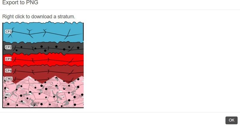
Fig. 12: Screenshot of the exportable file.
Once the stratigraphy has been completed, the user can question the MiCorr application to find case study(ies)/corrosion form(s) similar to the corrosion form newly built by clicking on the “Find similar” button (Fig. 13).
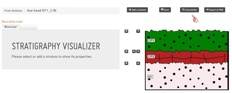
Fig. 13: Screenshot of the Search tool by Stratigraphy representation (binocular mode) showing the stratigraphy corresponding to the corrosion structure of Fig. 2 once each stratum has been characterized.
A new window opens, which gives proposals of stratigraphies from the MiCorr database that are the closest to the stratigraphy that has just been constructed (Fig. 14). The table provided gives on the left the values of the characteristics by default, those in blue being filled and those in grey being unfilled), and on the right for each proposed stratigraphy the matching score and information on the corresponding artefact. Note that in our example, stratigraphies documented on cross-sections are also listed.
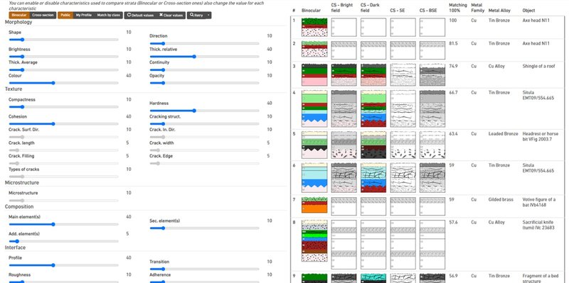
Fig. 14: Screenshot of the list of stratigraphies’ proposals from the MiCorr database that are the closest to the stratigraphy under construction using the default mode.
The user has the possibility to compare the stratigraphy studied to those obtained under binocular or cross-section modes, to those publicly available (online) or on the user’s profile. The user can also match strata of the stratigraphies by class. In each case, he.she has to retry the comparison process.
By
clicking on each digital stratigraphy and the additional information, the user
has access to the characteristics of the stratigraphy and the object sheet of
the corresponding artefact.
- Bertholon, R. 2001. Characterization and location of the original surface of corroded archaeological objects. Surface Engineering, 17 (3): 241-245.
- Bertholon, R. 2000. La limite de la surface d'origine des objets métalliques archéologiques, caractérisation, localisation et approche des mécanismes de conservation. PhD dissertation, University Paris 1 Panthéon-Sorbonne, France. Corrosion doctors: http://www.corrosion-doctors.org/pict-type.htm (accessed 10.19.2015).
- Degrigny C., Dillmann P., Gaspoz C. and Neff D., Exploitation and dissemination of MiCorr as a diagnostic support tool for heritage metals, Murray, A., & Vila, A. (2022). Diagnosis: Before, During, After. CONSERVATION 360º, (2), 459. https://doi.org/10.4995.360.2022.657201
- Valbi V. et al., MiCorr application: a diagnostic tool for corrosion forms on heritage metal artefacts, Young Professional Forum 2021, 88-95.


