Fragment of an Aegis of Neïth 1886.305.0096
Line. Pedersen (HE-Arc, Neuchâtel, Neuchâtel, Switzerland) & Christian. Degrigny (HE-Arc CR, Neuchâtel, Neuchâtel, Switzerland) & Valentin. Boissonnas (HE-Arc CR, Neuchâtel, Neuchâtel, Switzerland)
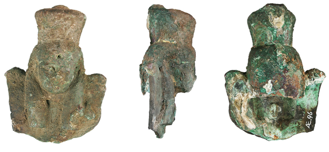
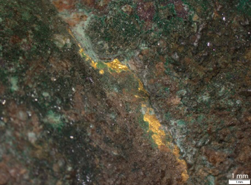
Fragment of an aegis surmounted by the head of Neith, the Egyptian goddess of war (Fig. 1). Traces of leaf gilding is still present in certain areas (Fig. 3). The lower part of the collar and the upper part of the crown are broken (Fig. 2 and 4). The surface is covered with a thick and hard, green-brown corrosion crust (Fig. 2, 3 and 4). A cross-section was studied on the lower edge that was broken after excavation. Dimensions: L = 96mm; W = 72mm; T = 40mm; WT = 216g.
sculpture
ancient Egypt
Purchased at the end of the 19th, probably from the art market. Date of excavation unknown.
None
Unknown
Bernisches Historisches Museum (BHM), Bern, Bern
Bernisches Historisches Museum (BHM), Bern, Bern
1886.305.0096
N/A
None.
 Credit He-Arc CR, L.Pedersen.
 Credit He-Arc CR, L.Pedersen.
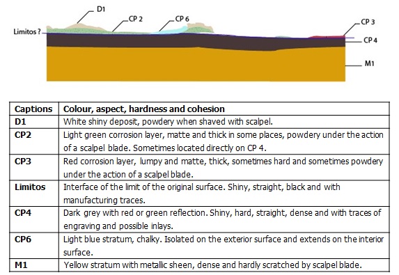
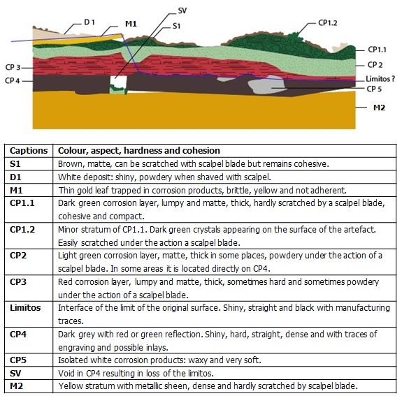
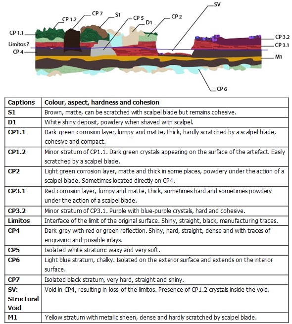
The schematic representation below gives an overview of the corrosion layers encountered on the aegis from a first visual macroscopic inspection.
 Credit He-Arc CR, L.Pedersen.
 Credit He-Arc CR, L.Pedersen.
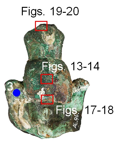
Only samples of corrosion products were taken. For sampling locations, see Figs. 2-5.
Leaded Bronze
As-cast, engraving, (glass?) inlay, gilding with gold foil.
None
HE-Arc CR, Neuchâtel, Neuchâtel
HE-Arc CR, Neuchâtel, Neuchâtel
April 11th 2017, chemical and molecular analyses
None.
Analyses performed:
X-ray Tomography of the entire object with MICRODETECT system: 1600 projections of 2000x2000pixels, V = 280kV, I = 100uA, filter of copper (0.5mm) and aluminium (2mm), integration time per projection: 3s/image x 2 images, total time acquisition: 1600 x 6s and distance source-detector: 1225mm. X-Ray Fluorescence (XRF) on the object without sampling under the corrosion crust and on cross-section with portable X-ray fluorescence spectrometer (NITON XL3t 950 Air GOLDD+ analyser, ThermoFischer®). X-Ray diffraction (XRD) on corrosion products sampled. Data collected was performed using Mo-Kα radiation (λ = 0.71073Å, beam diameter 0.5mm) and X-ray Diffraction (XRD) patterns measured on a Stoe Mark II-Imaging Plate Diffractometer System equipped with a graphite-monochromator. Two-dimensional diffraction images (10min per exposure) were obtained at an image plate distance of 200mm with a continued sample rotation. Resolution of Dmax 24.00 and Dmin 1.04Å and intensity integration performed over the entire image (360°).
The metal (M2 in Fig.9 and M1 in Fig. 10) was analysed on the broken edge of the bottom of the artefact where despite a highly corroded surface, the metal seems to be the best preserved. The XRF analyses revealed that the metal is a leaded bronze with remains of gold leaf on the surface (Table 1, Au was detected in the measurement spots 4,5 and 6) (Scott 2002; Gouda 2012; Mohammed 2012).
|
Elements mass (%) Areas |
Cu
|
Pb
|
Sn
|
Sb
|
Ag
|
Zn
|
Ni
|
Pd
|
Au
|
Si
|
Al
|
Fe
|
S
|
Ti
|
P
|
Cd
|
| 1 | 68.9 | 9.5 | 0.2 | 0.06 |
< |
< | 0.04 | < | < | 13.4 | 3.7 | 1.4 | 2.2 | 0.2 | 0.3 | < |
| 2 | 78.1 | 12.3 | 2.4 | 0.3 | 0.2 | < | 0.1 | < | < | 2.8 | 1.8 | 1.9 | < | 0.1 | < | < |
| 3 | 83.3 | 11.6 | 1.4 | 0.2 | < | < | 0.04 | < | < | 1.4 | 1.3 | 0.5 | < | 0.05 | < | < |
| 4 | 80.6 | 11.4 | 0.5 | < | 0.2 | 0.08 | 0.1 | 0.1 | 0.9 | < | < | 2.1 | < | 0.5 | < | 0.1 |
| 5 | 76.5 | 11.3 | 0.5 | < | 0.4 | 0.1 | 0.1 | 0.2 | 6.6 | < | < | 2.8 | < | 0.7 | < | 0.2 |
| 6 | 89.8 | 5.6 | 0.2 | < | 0.2 | 0.1 | 0.4 | 0.1 | 1.8 | < | < | 1.1 | < | 0.2 | < | 0.08 |
Table 1: Chemical composition of the aegis in the areas located on figures 2, 4 and 5. Method of analysis: portable XRF, acquisition time 60s. Areas 1-3: mode general metal, 20/20/20s. Areas 4-6: mode precious metal, credit MiCorr_HE-Arc CR, C.Degrigny.
The metal seems to be a leaded bronze with remains of gold leaf on the surface (Table 1).
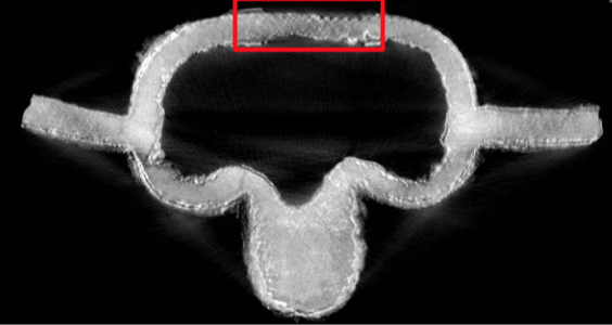
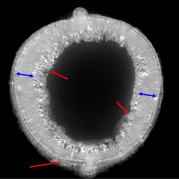
As indicated by the X-ray tomography, the metal of the aegis seems to be well preserved (Figs. 11-12).
 Credit Empa, M.Plamondon
Dendritic structure
Cu
Sn, Sb, Pb
None.
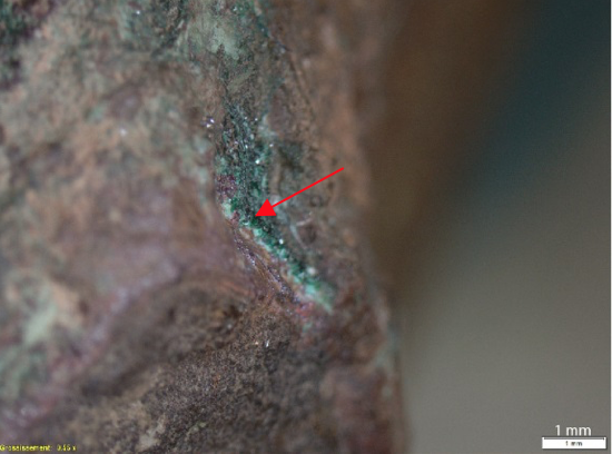
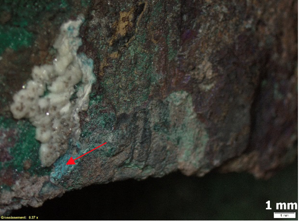
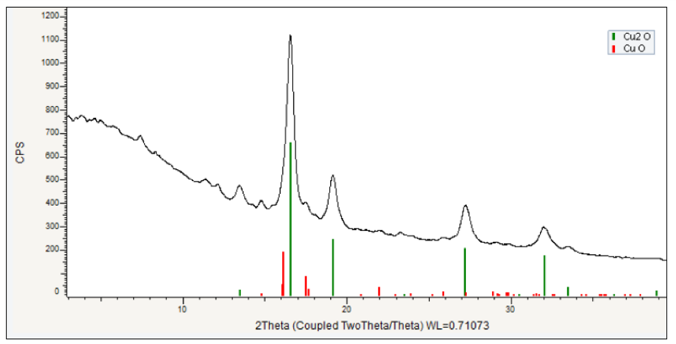
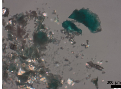
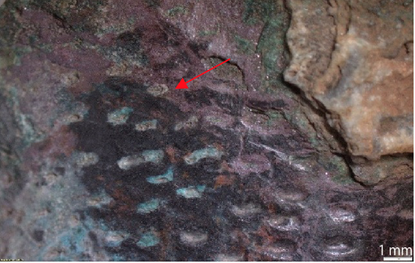
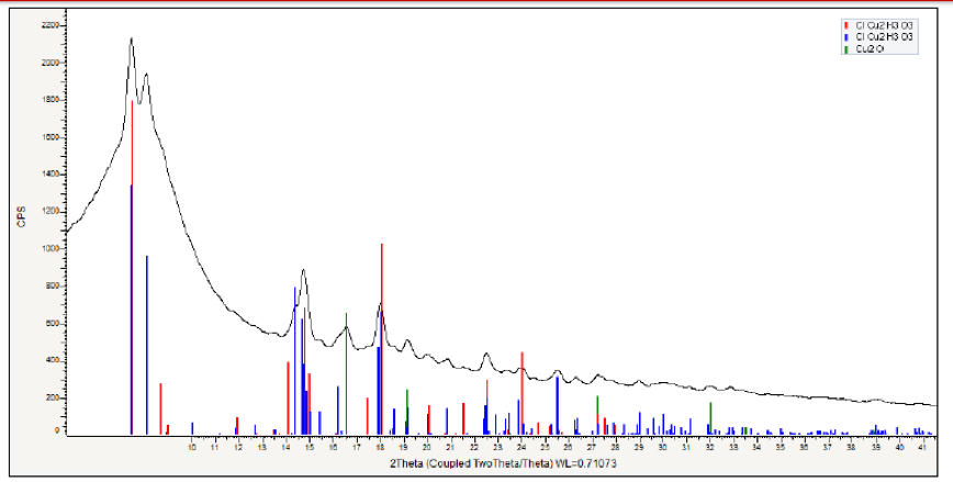
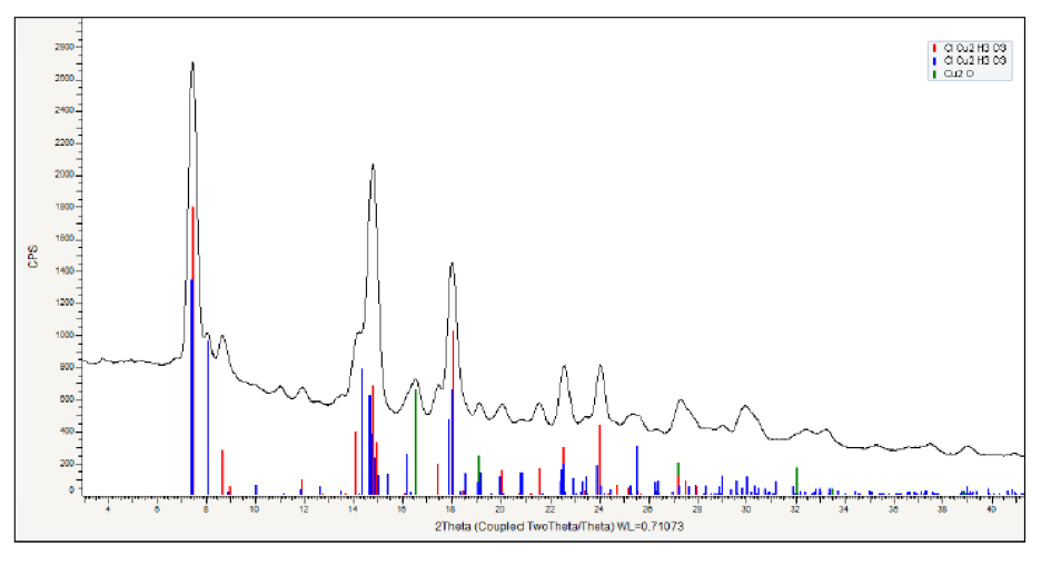
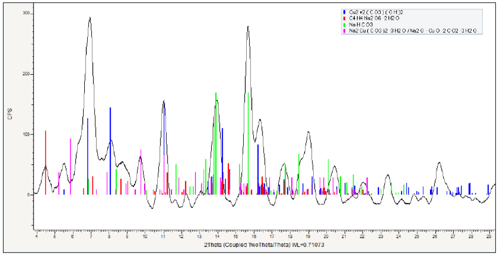
The corrosion crust covers the whole object and is heterogenous. It is formed by multiple layers which are particularly hard and can hardly be removed with the scalpel. The corrosion can be divided into three main layers: an outer green layer followed by a dense and hard red layer, followed by a black layer that contains corresponding markers and the limit of the original surface. In some areas this sequence is regular and clear. In other areas the limitos has been replaced by more porous green-red corrosion products which do not contain any corresponding markers. In certain areas the limitos and internal corrosion layers have been replaced by structural voids. XRD analysis (Table 2) of these different layers indicates that the upper hard and thick, green corrosion product (Figs. 13-14, CP1.1 and 1.2 in Figs. 6-7) is composed of copper oxychlorides: atacamite and paratacamite (Cu2Cl(OH)3) (Fig. 21). The next layer (CP2) is more powdery and light green in colour (Figs. 15-16). XRD analysis also identified this product as atacamite and paratacamite (Fig. 22). During the removal of the green and red corrosion layers we found a white and waxy corrosion product close to the original surface. This observation and the presence of high amounts of copper oxychlorides led us to identify this white corrosion product as nantokite (CuCl). The localized light blue corrosion product (CP6 in Fig. 8, CP1 in Fig. 10) present in one area on the back (Figs. 17-18) was identified as chalconatronite (Na2Cu(CO3)2·3H2O) (Fig. 23). The red corrosion layer (CP3) below the copper oxychlorides and above the dark black original surface (Figs. 19-20) was identified as a mixture of cuprite (Cu2O) as major coumpound and tenorite (CuO) as minor coumpound (Fig. 24). It is possible that the tenorite was a contamination from the black surface below the cuprite layer.
| Strata | Components |
| CP1.1 and CP1.2 | Paratacamite, Atacamite (Cu2Cl(OH)3) |
| CP2 | Paratacamite, Atacamite (Cu2Cl(OH)3) |
| CP4 | Cuprite (Cu2O), Tenorite (CuO) |
| CP6 | Chalconatronite (Na2Cu(CO3)2·3H2O) |
Table 2: Chemical composition of the corrosion products. Analytical method: XRD, credit MiCorr_Empa, A.Neels.
 Credit HE-Arc CR, L.Pedersen.
 Credit HE-Arc CR, L.Pedersen.
 Credit HE-Arc CR, L.Pedersen.
 Credit HE-Arc CR, L.Pedersen.
 Credit HE-Arc CR, L.Pedersen.
 Credit Empa, A.Neels.
 Credit Empa, A.Neels.
 Credit Empa, A.Neels.
Multiform
Type II (Robbiola)
The corrosion layers are thick and very hard due to the burial context which was probably rich in chlorides. From the top to the bottom of the corrosion layers, there is a large amount of dark and light green corrosion product identified as copper oxychlorides followed by a layer of red corrosion product identified as copper oxide (cuprite) and a dark red corrosion layer identified as copper oxide (tenorite). In certain localised areas we were able to identify chalconatronite, a light blue corrosion product typically formed by natron salt from the Egyptian soil. Due to the presence of manufacturing traces and engravings, the limit of the original surface is localised mainly in the dark red corrosion layer. In certain areas there are remains of gilding-foil identified as gold by XRF elemental analysis. The foil is preserved on the top of the corrosion layer. Because gold is a noble metal, it had not corroded and was lifted by the corrosion products of the copper alloy. Thus, the limit of the original surface is displaced in some areas (Fig. 6, see limitos).
None.
Based on the observation of the broken edge and the tomography we are able to determine that the remaining metal is well preserved. The alloy was identified by XRF as a leaded copper alloy. The corrosion stratigraphy and the presence of a large amount of dark and light green powdery corrosion product identified as copper chlorides indicate a Robbiola Type 2 corrosion. In some areas the limit of the original surface is well preserved and reveals a highly decorated surface. In other areas the latter did not survive and was replaced by structural voids or porous red-green corrosion products. The nature of the different corrosions products and the metal, match with what was found in other studies of Egyptian bronzes (Scott 2002; Gouda 2012). Concerning the presence of tenorite on the original surface, tenorite generally forms if the object is exposed to high temperature or if it was intentionally heated to patinate the surface. In ancient Egyptian, heat was typically used to obtain black bronze. Tenorite is known as a corrosion product on other Egyptian black bronzes (Mohammed 2012). It is likely that the Aegis has been artificially patinated. The fact that it was most certainly partly gilded reinforces this hypothesis to reach colour contrasts.
References on object and sample
References object
1. Scott, D. and Swartz Dodd, L. (2002) Examination, conservation and analysis of a gilded Egyptian Osiris". Journal of Cultural Heritage, 3, 333-345.
2. Gouda, V.K. et al. (2012) Characterization of Egyptian bronze archaeological artifacts”. Surf. Interface Anal., 44, 1338-1345.
3. Mohammed, W. and Darweesh, S. (2012) Ancient Egyptian Black-Patinated Copper alloys". Archaeometry, 54, 175-192.