Button Yaj.96.B20.D1.28.button-a
Ahmad. Abu-Baker (Yarmouk University, None)
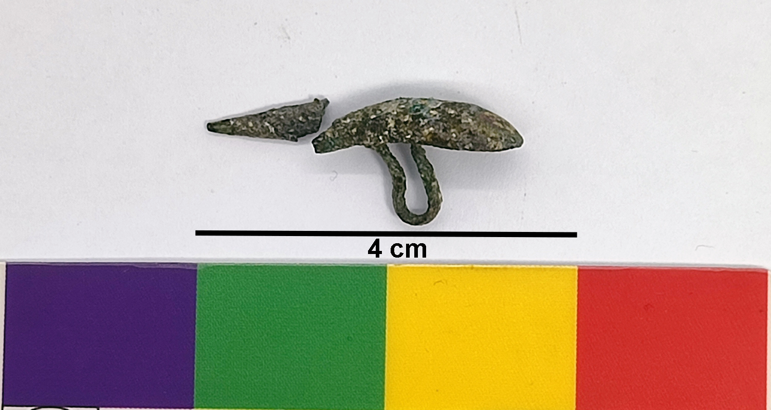
A broken metallic oval shank button. The button's surface is hetereogeously corroded and has green, blue-green, and red-brown corrosion products, with the presence of light yellow soil sediments. Its sharp tip is broken and very brittle (Fig. 1).
clothing element
Khirbet Yajuz, Jordan
Excavation 1996
Byzantine
Soil
The Archaeological Museum at the University of Jordan, Amman, Amman
Department of Antiquities of Jordan
Yaj.96.B20.D1.28.button-a
N/A
None.
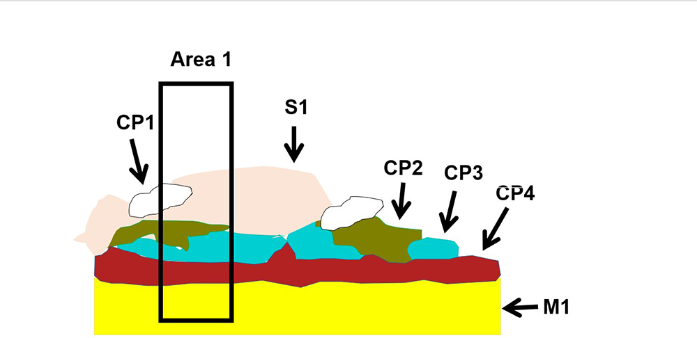
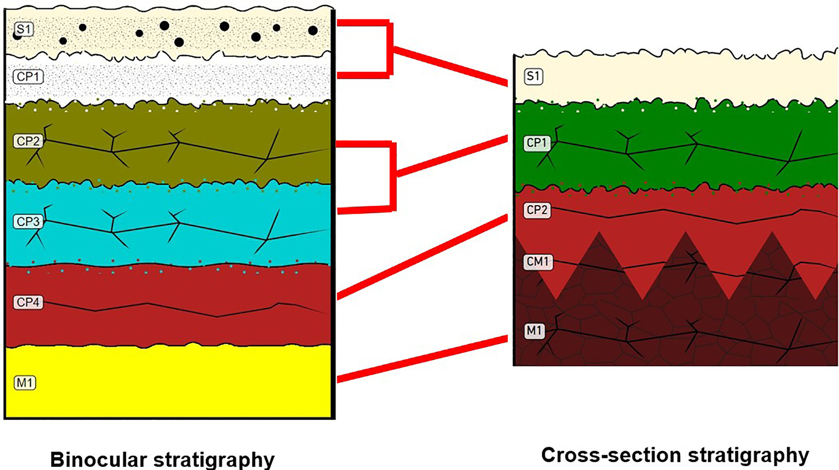
The schematic representation below gives an overview of the corrosion structure(s) encountered on the button from a first visual macroscopic observation:
|
Strata |
Type of strata |
Principle characteristics |
|
S1 |
Soil |
Light brown soil |
|
CP1 |
Corrosion product |
White corrosion spots |
|
CP2 |
Corrosion product |
Olive-green corrosion layer |
|
CP3 |
Corrosion product |
Turquoise-blue corrosion product |
|
CP4 |
Corrosion product |
Red-brown corrosion product |
|
M1 |
Metal |
Yellow metal |
Table 1: Description of the principal characteristics of the strata as observed under binocular and described according to Bertholon's method.
A cross-section taken from the broken tip of the button.
Cu Zn alloy
Cast and annealed
None
The Archaeological Museum at the University of Jordan, Amman, Amman
May 2023. Sampling aimed to study the composition, corrosion, and microstructural properties of the artefact.
None.
Analyses performed
- Non-Invasive approach
XRF: with handheld portable X-ray fluorescence spectrometer (NITON XL3t 950 Air GOLDD+, Thermo Fischer®). General Metal mode, acquisition time 60s (filters: Li20/Lo20/M20).
- Invesive approach
- Metallography: The polished cross-section was observed by optical microscopy (OM) in bright and dark field modes using a Leica DM/LP polarizing light microscope. The OM in dark field mode allowed us to observe and quantify morphological, textural, microstructural and interfacial features of the strata. The cross-section was then etched with ammonium persulphate 10% in water to examine the microstructure using bright-field illumination, which helped to identify the manufacturing technique of the artifact.
- SEM-EDS: the sample was coated with a Pt layer and the analysis of the corrosion layers and internal alloy was performed using a SEM-FEG JEOL 7001-F equipped with a silicon-drift EDS Oxford detector (Aztec analysis software) with an accelerating voltage of 20 kV and probe current at about 9 nA. The relative error is considered of about 10% for content range <1wt%, and 2% for content range of >1wt%.
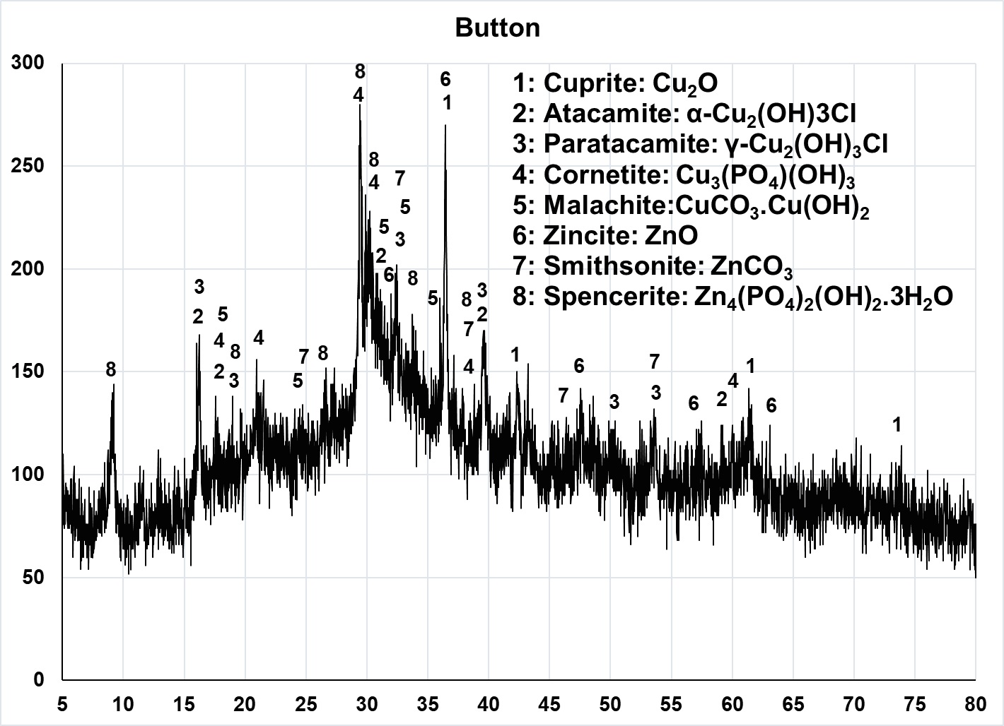
- XRD: The mineralogical composition of the corrosion products of button-a was examined by X-ray diffraction (XRD) analysis using a Shimadzu LabX, XRD-6000 X-ray diffractometer. To minimize the amount of corrosion products taken for the analysis, a small amount was scratched off from the surface of the artifact, dispersed in ethanol, then spread on a microscopic glass slide, the ethanol was allowed to dry off, then the glass slide covered with the thin layer of corrosion products powder was placed in the XRD instrument for analysis. The X-ray was generated from an anticathode copper (Cu) tube with a wavelength CuKα = 1.54178 A. The operation was at 40 kV and 30 mA, the 2θ analysis range was 5–80o, and the scan speed was 2o per minute.
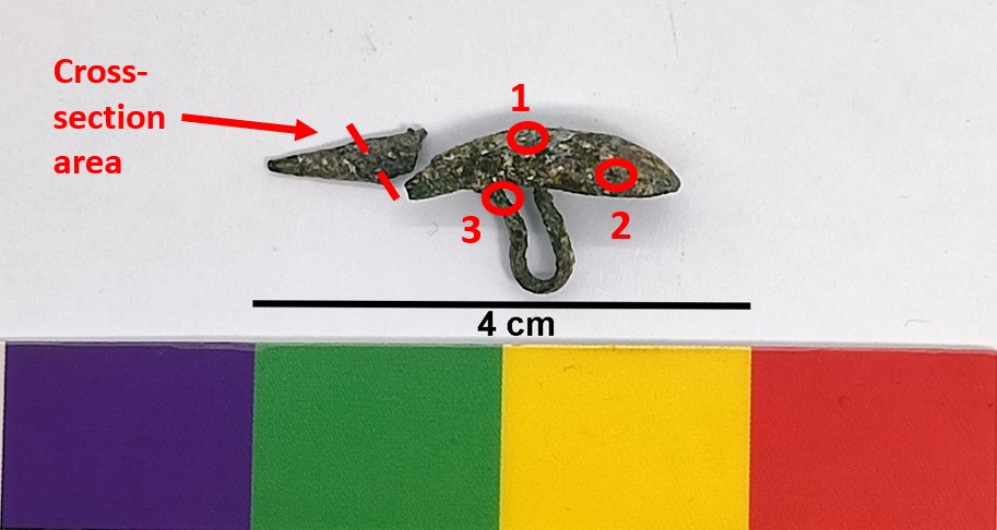
XRF analyses were carried out on the surface of the button-a (Fig. 2). All strata (deposit, corrosion products and metal) were analyzed at the same time. Button-a is presumably made of an α-brass (Cu-Zn) alloy. The amount of zinc in the alloy is relatively high. The presence of P and Ca could be attributed to the hydrolysis of hydroxyapatite (Ca5(PO4)3OH) from the skeletal materials in the neighboring bodies where the artifacts were excavated (Fan et al. 2020; Abu-Baker and Khalil 2022; Abu-Baker 2023b). The Si, Al, Fe are the elements of soil deposits, while the S presumably indicates either copper sulfide corrosion or the use of copper sulfide ores in the production of the artifacts (Rostoker et al. 1989).
|
Button a |
|||
|
Element |
Button a.1 |
Button a.2 |
Button a.3 |
|
Cu |
65 |
70 |
64 |
|
Zn |
15 |
14 |
19 |
|
Pb |
1 |
1.2 |
0.6 |
|
Sn |
0.2 |
1.7 |
0.5 |
|
Si |
11 |
7 |
10 |
|
P |
1.7 |
2 |
1 |
|
Fe |
0.3 |
0.3 |
0.3 |
|
S |
1.5 |
0.4 |
0.7 |
|
W |
2 |
1.7 |
3.5 |
|
Al |
2.3 |
|
|
Table 2: Chemical composition of the surface of button-a analyzed by XRF at three representative points shown in Fig. 2.
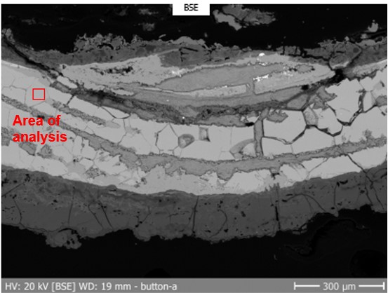
The EDS analysis of the internal alloy of button-a showed that it is made from a brass (Cu-Zn) alloy (Fig. 6). The result of the SEM-EDS analysis is in a good agreement with the non-invasive XRF analysis, except for Pb and Sn which might be due to soldering remains.
| Element | Wt % |
| Cu | 77.5 |
| Zn | 22.5 |
Table 3: EDS analysis result of the internal alloy of button-a.
The OM examination of the etched cross-section of button-a revealed that it was annealed, as indicated by its recrystallized microstructure and annealing twins (Fig. 7). The SEM micrograph also shows the extension of the corrosion process into the intergranular boundaries of the internal alloy (Scott 1991: 7–8; Scott & Schwab 2019: 154).
 Credit HEI Arc, C.Cséfalvay.
Recrystallized equiaxed α-grains together with annealing twins and white lead globules
Cu
Zn
None.
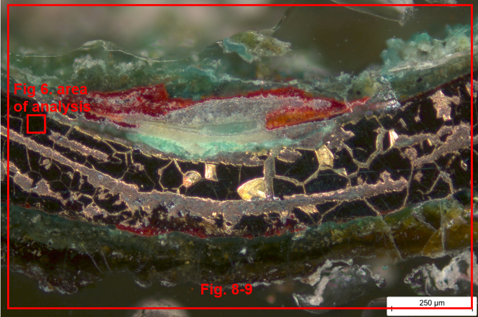
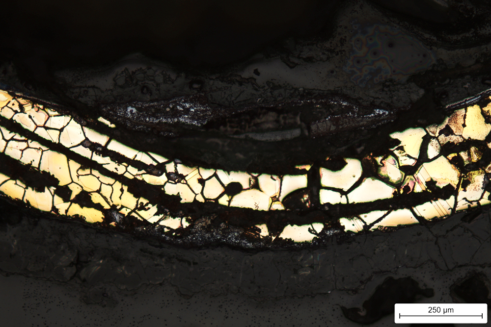
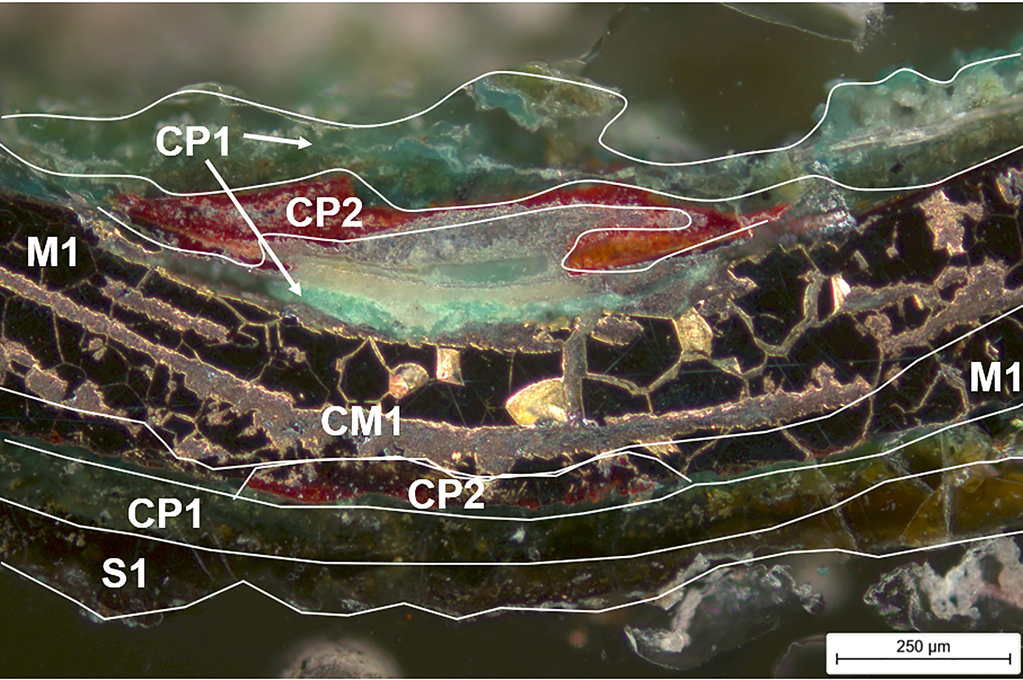
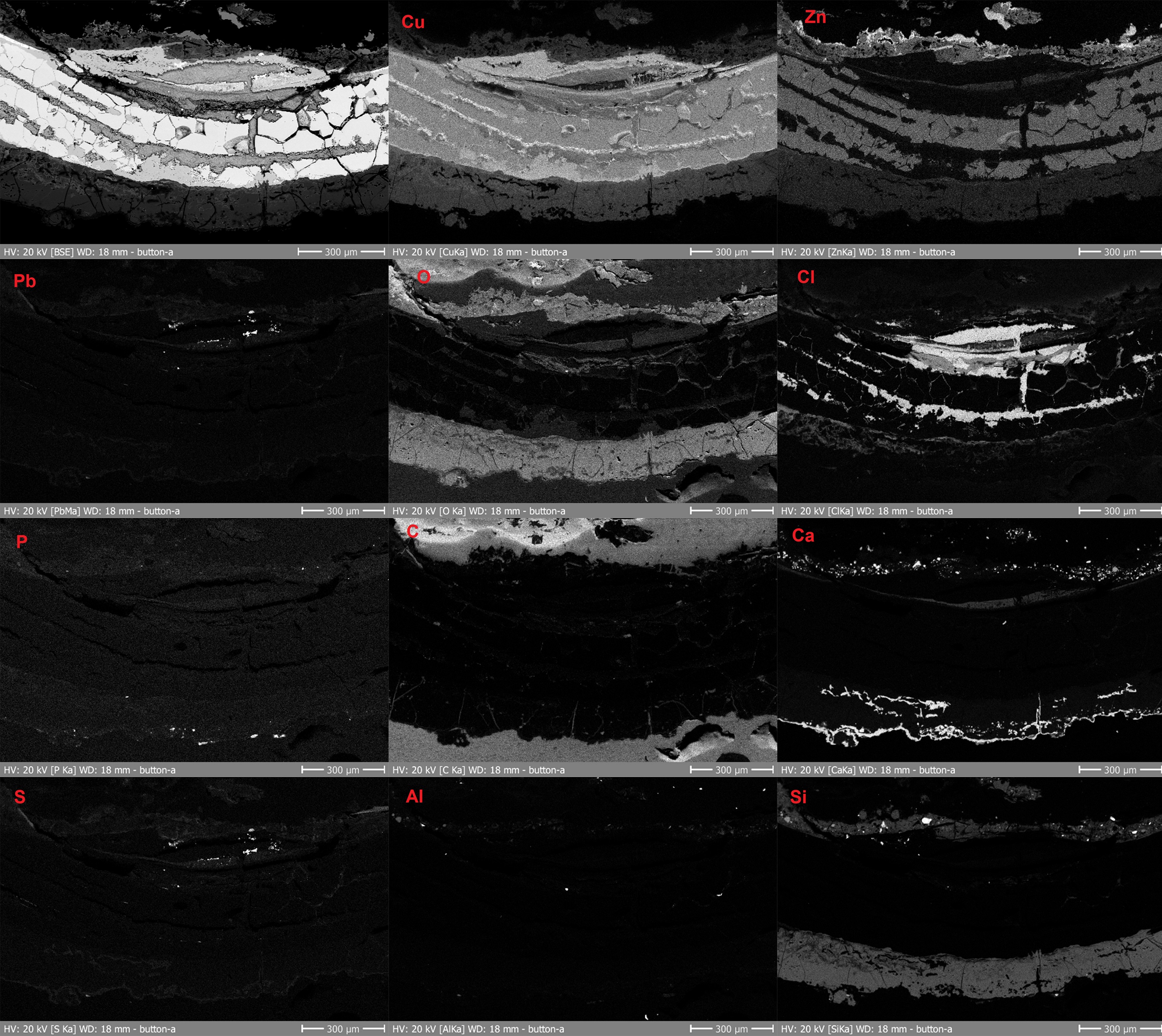
The OM examination (Fig. 8) and EDS elemental mapping (Fig. 9) of the button-a showed that the CP1 corroded layer contains Cu, Zn, Pb, O, P, Si, Ca, and Al. The presence of P and Ca in the CP1 layer could be attributed to the hydrolysis of hydroxyapatite (Ca5(PO4)3OH), which induced the formation of copper minerals containing them as indicated in XRD spectrum (cornetite (Cu3(PO4)(OH)3,Fig. 10) (Fan et al. 2020; Abu-Baker and Khalil 2022; Abu-Baker 2023b). Ca could have also come from the calcite in the burial context of the archaeological site. Si and Al in the S1 and CP1 are the elements of soil deposits, while the CP2 layer is rich in Cu and O, which indicates the presence of cuprite (Cu2O), confirmed by XRD spectrum (Fig. 10). The original surface has been preserved and corresponds to the interface between CP1 and CP2. The corroded area in CM1 has more Cu and Cl while Zn is missing, which indicates an internal dealloying and selective removal of the more anodic metal (Zn), i.e., dezincification by the corrosion processes. The dezincification of the CM1 layer reaches the internal alloy as appearing in the EDS mapping image and OM dark-field micrograph. In the presence of chloride ions in the corrosive environment, the diffusion of anodic metal, zinc, from the alloy is higher than that of copper; its Zn2+ ions have smaller radius (0.070 nm) than Cu+ ions (0.096 nm), therefore are easier to diffuse and react with the corrosive burial soil to form corrosion products that precipitate on the outer surface of the artifact or the surrounding soil (Ravichandran and Rajendran 2005; Abu-Baker et al. 2021). The EDS mapping images show the presence of small inclusions containing sulfur (S), which indicate that the copper ores used for the production were either copper sulfides or a mixture of copper sulfides and oxides (Rostoker et al. 1989). XRD revealed the presence of other corrosion products expected on such an artifact: malachite (CuCO3.Cu(OH)2), atacamite (α-Cu2(OH)3Cl), paratacamite (γ-Cu2(OH)3Cl), zincite (ZnO), smithsonite (ZnCO3) and spencerite (Zn4(PO4)2(OH)2·3H2O) (Fig. 10). The presence of atacamite/paratacamite (Cu2(OH)3Cl) and the absence of nantokite (CuCl) in the XRD results suggest that the initially formed nantokite in the burial soil underwent oxidative hydrolysis, which induced the formation of atacamite/paratacamite under the uncontrolled storage conditions. The artifact has either been stabilized by this reaction or is in a metastable state if nantokite is present deeper in the alloy such that it was not collected in the samples obtained for XRD analysis (Scott 1990). The diffused zinc from the alloy reacted with the corrosive burial soil and after a prolonged exposure formed smithsonite and spencerite.
 Credit HEI Arc, C.Cséfalvay.
 Credit HEI Arc, C.Cséfalvay.
Multiform - selective
Dezincification
None.
The observation under binocular microscope identified 4 CPs of different colors, and the cross-section observation using the dark-field illumination of the optical microscope identified 2 CPs and a CM. With binocular microscope, it is possible to differentiate strata according to texture and light color changes that do not always correspond to significative changes in chemical composition, thus leading to a regrouping of several strata into one in the cross-section observation and physicochemical characterization. The differences between the two observation modes could also be explained by different locations of observation. The S1 and CP1 strata under binocular microscope could be grouped and correspond to S1 in cross-section. The CP2 and CP3 under binocular microscope could be grouped and correspond to CP1 in cross-section. Similarly, the CP4 under binocular microscope probably corresponds to CP2 in the cross-section. Finally, the corroded metal (CM) zone can only be observed on a cross-section. It is characterized by corrosion that has developed within the metal while preserving remnants of the original metallic structure, i.e., the dezincified copper-rich network, and can therefore only be observed on a cross-section.
Button Yaj.96.B20.D1.28.button-a is made of an α-brass alloy (Cu-Zn) with high zinc content (22.5%). Its metallographic examination revealed recrystallized equiaxed α-grains together with annealing twin, suggesting that the repeated cycles of working and annealing were finished by an annealing process. The micrographs also show the extension of the corrosion process into the intergranular boundaries of the internal alloy. Observing the corrosion structure in the cross-section allowed us to identify the original surface of the button that has been preserved and corresponds to the interface between CP1 and CP2. The corrosion stratigraphy and microstructural properties of the button showed that the corrosion structures contained the phenomenon of dezincification commonly observed in brasses, i.e., a selective leaching of the more active metal, zinc, from the alloy. The elemental distribution of Cu and Zn in the EDS elemental maps showed patterns of depletion across the alloy. The insoluble phosphate corrosion products on the surface of the artifact improved its stability against dezincification and active chloride-based corrosion present in the internal pits. The investigation of the internal corrosion was complementary to that of external corrosion and helped provide complete information about the corrosion of this artifact, which allowed corrosion stratigraphy representations to be created using the MiCorr modeling program.
References on objects
Khalil, L.(1998) University of Jordan excavations at Khirbat Yajuz. Annu. Dep. Antiq. Jordan (ADAJ) 42, 457–472.
References on analytical methods and interpretation
1. Abu-Baker, A.N. (2023a) Analytical investigation and electrochemical conservation treatment for archaeological copper alloy artifacts from Jordan. Conserv. Patrim. 42, 38–55.
2. Abu-Baker, A.N. (2023b) A technical examination of the corrosion and microstructural features of copper alloy artifacts from the Byzantine period at Khirbet Yajuz, Jordan. Metallogr. Microstruct. Anal. 12, 276–288.
3. Abu-Baker, A.N., Khalil, L.A. (2022) An analytical study of the corrosion behavior and microstructural properties of a group of copper alloy artifacts from the Khirbet Yajuz archaeological site, Jordan. In: Mardikian, P., Näsänen, L., Arponen, A. (eds.) Metal 2022: Proceedings of the Interim Meeting of the ICOM-CC Metals Working Group, pp. 221–230. International Council of Museums – Committee for Conservation (ICOM-CC) and The National Museum of Finland, Helsinki.
4. Abu-Baker, A.N., Khalil, L.A., Gonmeen, T. (2021) A multi-analytical exploration of the chemical composition, microstructural properties and corrosion inhibiting treatment for an archaeological brass censer from Umm Zuwaytinah, Amman. Nucl. Instrum. Methods Phys. Res. B 502, 73–79.
5. Bertholon, R. (2000) La limite de la surface d’origine des objets métalliques archéologiques, caractérisation, localisation et approche des mécanismes de conservation (The Limit of the Original Surface of Archaeological Metal Objects: Characterization, Location and Approach to Conservation Mechanisms), in French. Ph.D. Dissertation, University Paris 1 Panthéon-Sorbonne, France.
6. Bertholon, R. (2001) Characterization and location of the original surface of corroded archaeological objects. Surf. Eng. 17(3), 241–245.
7. Degrigny, C., Dillmann, P., Gaspoz, C., Neff, D. (2022) Exploitation and dissemination of MiCorr as a diagnostic support tool for heritage metals. Conserv. 360º 2, 459.
8. Degrigny, C., Gutknecht, N., Valbi, V., Neff, D., Dillmann, P., Berranger, M., Gaspoz, C., Letourmy, B. (2025) Transdisciplinary collaboration for the multi-scale description of corrosion structures in metallic heritage. In: Neff, D., Grassini, S., Watkinson, D., Emmerson, N. (eds.) Bridging the Gap: Corrosion Science for Heritage Contexts, EFC Series, vol. 73, pp. 147–163. Woodhead Publishing in Materials, Cambridge.
9. Eary, L.E. (1999) Geochemical and equilibrium trends in mine pit lakes. Appl. Geochem. 14(8), 963–987.
10. Fan, X., Wang, Q., Wang, Y. (2020) Non-destructive in situ Raman spectroscopic investigation of corrosion products on the bronze dagger-axes from Yujiaba site in Chongqing, China. Archaeol. Anthropol. Sci.
11. Graziani, V., Iorio, M., Albini, M., Riccucci, C., Di Carlo, G., Branchini, P., Tortora, L. (2020) Metals and environment: chemical outputs from the interaction between gilded copper-based objects and burial soil. Front. Mater. 7, 32.
12. Rostoker, W., Pigott, V.C., Dvorak, J.R. (1989) Direct reduction to copper metal by oxide–sulfide mineral interaction. Archeomaterials 3(1), 69–87.
13. Scott, D.A. (1990) Bronze disease: a review of some chemical problems and the role of relative humidity. J. Am. Inst. Conserv. 29(2), 193–206.
14. Scott, D.A., Schwab, R.(2019) Metallography in Archaeology and Art, p. 154. Springer, Cham.