Rain gutter fragment
Christian. Degrigny (HE-Arc CR, Neuchâtel, Neuchâtel, Switzerland) & Mathea. Hovind (University of Oslo, Department of archaeology, conservation and history (IAKH-UiO), Oslo, Oslo, Norway)
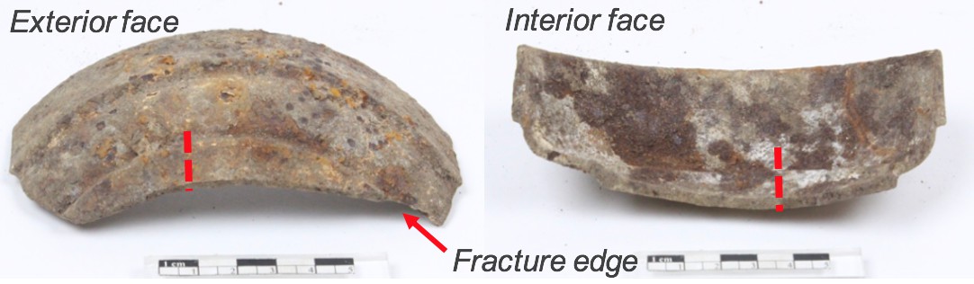
Rain gutter fragment (Fig. 1), possibly part of the extension of a roof drain pipe. Both the exterior and interior surfaces are covered by heterogeneous corrosion crusts. The underlying metal seems however to be well preserved, including features such as a difference in thickness etc. Dimensions: L = 55mm; W (interior) = 120mm; Tmax. = 6mm; WT = 176g.
Architectural element
Château de Germolles, Mellecey, Bourgogne, France
Date unknown
Modern Times
19th - 20th century
Outdoor atmosphere
Haute Ecole Arc Conservation-Restauration
Château de Germolles, Mellecey, Bourgogne
No inventory number.
No recorded conservation data.
Nothing to report.
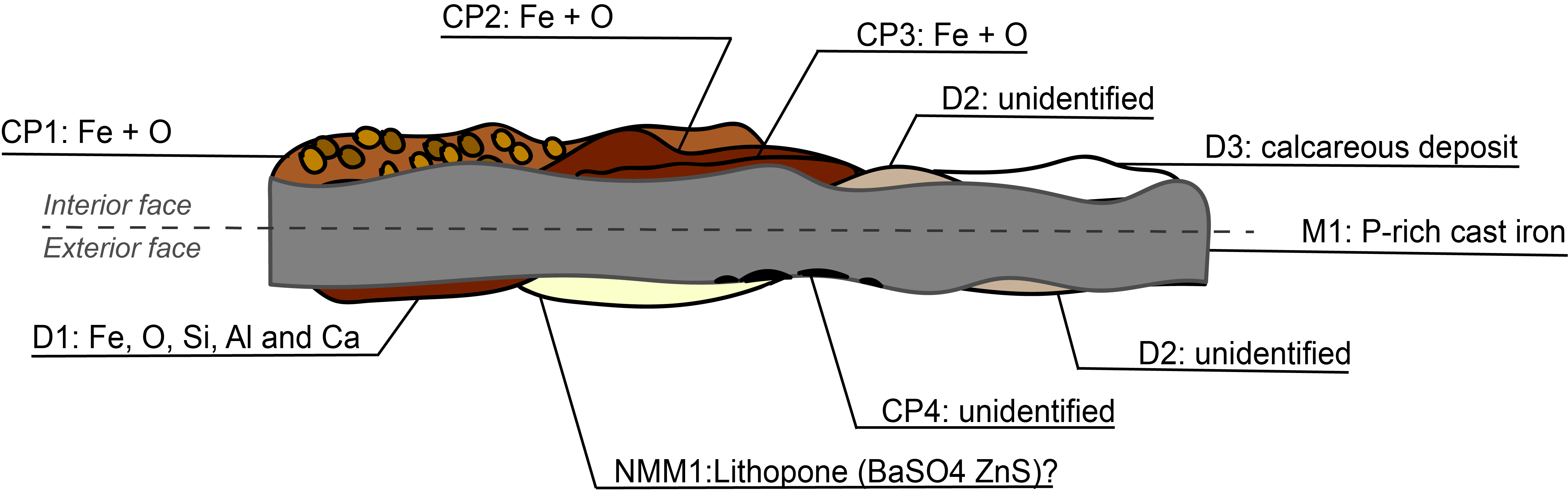
The schematic representation below (Fig. 3) gives an overview of the strata encountered by visual macroscopic observation.
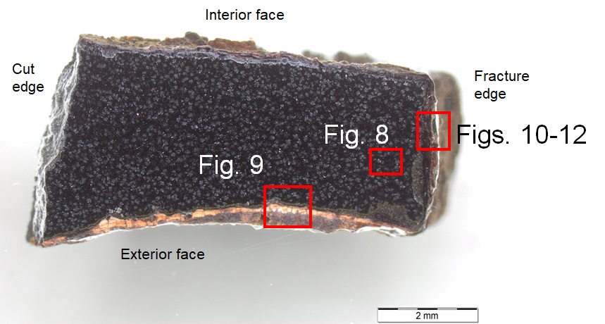
The sample consists of a rectangular section (Fig. 4) which was cut out from the fractured edge of the gutter fragment. It is representative of three surfaces: the exterior and interior surface, as well as the fracture edge. Dimensions: L = 7mm; Wmax. = 5mm; Tmax. = 4mm (approx.).
Grey cast iron
Cast
CIG2018 (Cast Iron Gutter, sampled in 2018)
Haute Ecole Arc Conservation-Restauration
Haute Ecole Arc Conservation-Restauration
March 2018, study of corrosion stratigraphy and chemical analyses
The fact that the artefact was considered a test material enabled extensive sampling that would not otherwise be possible.
Analyses performed:
Metallography: microscope: Leica DMi8 (a metallographic, inverted, reflected light microscope) with magnification up to 500X. Camera: Olympus SC50 connected to the software “Olympus Stream”, version 1.9.4. Illumination modes: bright field and cross-polarized light. The metal is unetched.
SEM-EDS: instrument: Jeol 6400; voltage: 20 kV; working distance: 18 and 24mm; sample preparation: palladium depot.
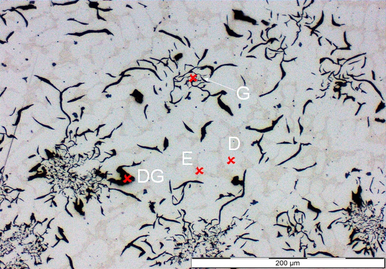
The metal is a P-rich grey cast iron with Si and Mn (Fig. 7). Its microstructure is characterized by evenly distributed graphite flakes in a matrix composed of dendrites and an interdendritic eutectic phase (Fig. 8). What appears to be irregular graphite flakes / porosity is in fact deformed graphite flakes; graphite is soft and prone to destruction by smearing and/or preferential removal during polishing (Scott 1991).
The dendrites appear light grey under polarized light, while the eutectic phase appear light brown (Fig. 8). The eutectic phase is rich in Fe and P and contains small amounts of C and Si, whereas the dendritic phase contains much less P (Table 1).
|
Elements mass % Phase |
Fe |
C |
P |
Si |
|
Eutectic phase |
78 |
7 |
14 |
0.5 |
|
Dendritic phase |
91 |
5 |
0.5 |
3 |
Table 1: Chemical composition of the matrix (eutectic and the dentritic phase). Method of analysis: SEM-EDS. Lab. of Electronic Microscopy and Microanalysis, Néode, HEI Arc, credit MiCorr_HEI Arc, C.Csefalvay.
* The value is the calculated average of three analyses of the same feature, but in different areas.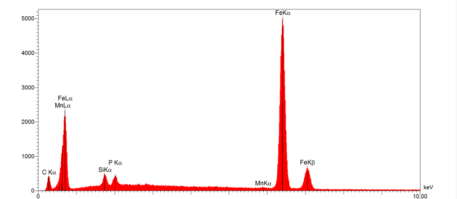 Credit HEI Arc, C.Csefalvay.
Dendritic structure with graphite flakes and a P-rich eutectic phase
Fe
C, Si, P, Mn
Nothing to report.
The exterior face (Figs. 2, 4 and 9) consists of a white / light yellow cracked layer (NMM1 in Fig. 5) superimposed by a layer of deposit mixed with orange-red corrosion products (D1 in Fig. 5). Punctual analysis by SEM-EDS (Table 2) revealed that the white / light yellow layer is rich in Ba, O, S, Fe, C and Zn. It has a chemical composition similar to Lithopone (BaSO4,ZnS), a preparatory paint layer. Fe is probably a contamination from the superimposed porous deposit / corrosion product D1 (Table 2). The latter (D1) is Fe- and O-rich and contains Si, Al and some Ca, in addition to a range of elements (K, P, Na, Cl, S and Ti) present in minor amounts (Table 2). A thin layer of corrosion products (CP1) is located just beneath the paint layer, appearing dark grey under polarized light (Fig. 9). This layer is followed by a corroded metal phase (CM1). Their exact composition was not analyzed but is likely to correspond to the corroded metal phase of the fracture edge, described below.
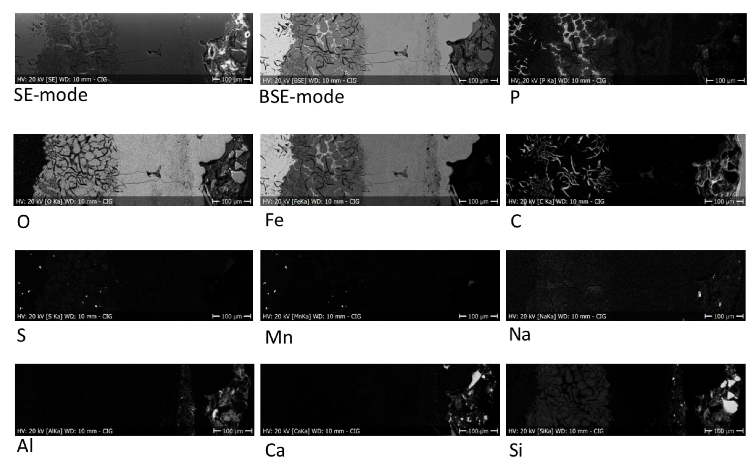
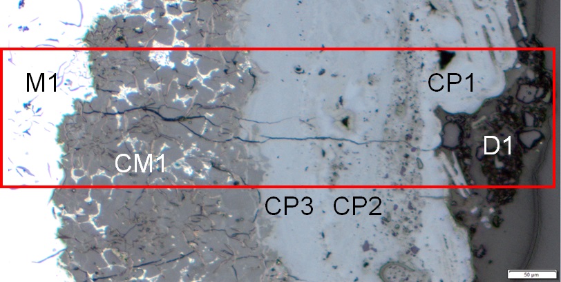
The interior face (Figs. 2 and 4) shows similar characteristics but does not include a white layer similar to NMM1. The fracture edge however (Figs. 2, 4 and 10), shows a more complex stratigraphy consisting of a dense product layer which can be further divided into two individual strata (CP3 and CP2), superimposed by a porous corrosion crust appearing orange under polarized light (CP1) (Fig. 11). The corroded metal (CM1) is located just beneath CP3 and contains remnants of the P-rich eutectic phase (Figs. 10-12). The M/CP ratio (metal to corrosion products) is rather high, implying extensive internal corrosion. Furthermore, a simple crack is traversing the corrosion layers – indicating a fragilization of the structure. As for the composition of the corrosion products CP1, CP2 and CP3, they all contain Fe and O (Fig. 12). A marbling effect within CP2 and CP3 indicates a variation in the concentration of Fe and O (particularly visible in bright field - Fig. 10). The white deposit (D1 in Fig. 6) might originate from exposure to calcareous water (Table 2). The presence of exogenous elements such as Si, Ca, Al, Na and O (Table 2) was confirmed by elemental mapping (Fig. 12).
|
Elements mass % Stratum |
Fe |
O |
Ba |
C |
Si |
S |
Zn |
Al |
Ca |
P |
K |
Na |
Cl |
Ti |
|
Deposit (D1) |
22 |
35 |
- |
26 |
10 |
0.3 |
- |
3 |
1 |
0.8 |
0.8 |
0.5 |
0.4 |
0.1 |
|
Paint layer (NMM1) |
10 |
23 |
37 |
9 |
0.5 |
12 |
7 |
- |
1 |
- |
- |
- |
- |
- |
Table 2: Chemical composition of the strata from Fig. 9. Method of analysis: SEM-EDS. Lab. of Electronic Microscopy and Microanalysis, Néode, HEI Arc, credit MiCorr_HEI Arc, C.Csefalvay. *The value is the calculated average of three analyses of the same feature, but in different areas.
 Credit UiO-IAKH, M.Hovind.
Fig. 9: Micrograph of the metal sample from Fig. 4 (detail), unetched, polarized light, 5x. The stratigraphy of the exterior surface, from top to bottom: the metal (M1) in grey, a layer of corroded metal (CM1) followed by a thin layer of CP1, and a white cracked layer (NMM1) superimposed by a porous dark-red deposit (D1),
 Credit UiO-IAKH,M.Hovind
Fig. 10: Micrograph of the metal sample from Fig. 4 (detail), unetched, bright field. From left to right: intact metal (M1) in white, followed by preferentially corroded metal (CM1) and dense product layers (CP3 and CP2) in various shades of grey. CP1 is slightly porous and covered by grain-like particles (D1). The area selected for elemental chemical distribution (Fig. 12) is marked by a red rectangle. A simple crack is traversing the corrosion layers,
 Credit UiO-IAKH, M.Hovind.
Multiform
?
Nothing to report.
The schematic representation of corrosion layers integrating additional information based on the analyses carried out is given in Fig. 13.
The rain gutter fragment is a grey cast iron with a microstructure consisting of graphite flakes and a P-rich eutectic phase. The exterior surface contains a preparatory paint layer, located beneath a layer of corrosion products mixed with soil. It seems likely that the cast iron gutter has been covered with a protective paint layer (e.g. Lithopone) to slow down the rate of atmospheric corrosion. The presence of Lithopone reinforces the suggested dating of the artefact (20th century) as this pigment was developed and used from the 1880s and onwards (Lithopone 2007). However, it seems that the protective layer has none or only very limited effect as (pitting) corrosion is present also in these areas.
The corrosion layers consist mainly of Fe and O, indicating atmospheric corrosion with presence of only a very small amount of contaminants/pollution. The scattered white deposit is possibly originating from exposure to calcareous water as it is localized mainly on the interior face of the fragment, where rain water would hit the metal before entering the ground.
| References on object and sample |
|
References sample |
|
References on analytic methods and interpretation |
|
|