Moil chisel DEV 995 762 PR
Marianne. Senn (EMPA, Dübendorf, Zurich, Switzerland) & Christian. Degrigny (HE-Arc CR, Neuchâtel, Neuchâtel, Switzerland)
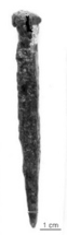
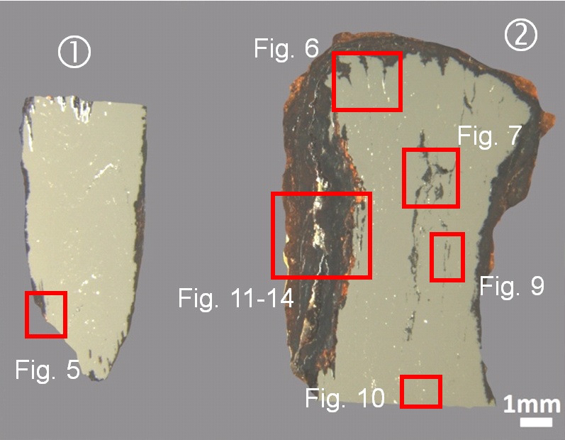
Moil chisel, the square shaft is rounded near the point, the head is concave and shows traces of flattening (Fig. 1). The black colour of the surface is due to the conservation treatment (see below).
Tool
Settlement Develier, Courtételle, Jura, Switzerland
Excavated in 1995, farm 1
Early medieval times
Soil
Office de la Culture, Porrentruy, Jura
Office de la Culture, Porrentruy, Jura
DEV 995/762 PR
Conserved between 1995 and 2000: desiccation below 80°C, mechanical cleaning, passivation with tannic acid and protection with Paraloid B72® (Eschenlohr et al. 2007, 75).
Nothing to report.
Stratigraphic representation: none.
 Credit HE-Arc CR.
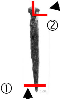
Two samples were taken on both extremities of the chisel (Fig. 2). They show the remaining metal covered by thick and cracked corrosion crusts (Fig. 3).
Steel
Welded
DEV 762
Empa (Marianne Senn)
Office de la Culture, Porrentruy, Jura
2000, metallography and chemical composition of the metal
Nothing to report.
Analyses performed:
Metallography (nital etched and etched with Oberhoffer’s reagent), Vickers hardness testing, LA-ICP-MS, SEM/EDS.
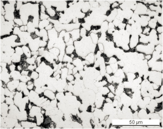
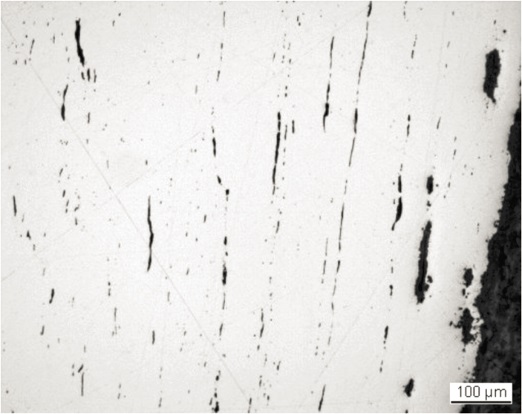
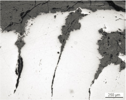
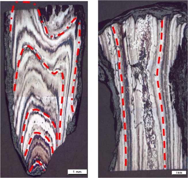
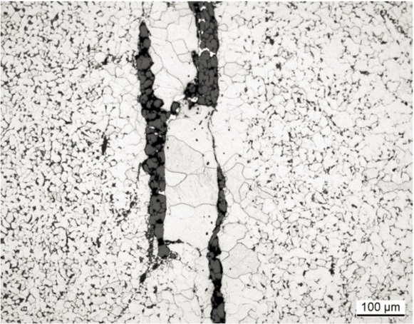
The remaining metal (M1) is a soft steel rich in P, Ni and As (P 0.1, Ni 0.2, As 0.1 mass%, Table 1). This composition and the ratio Ni/Co is typical for metal worked in the smithies of the settlement Develier-Courtételle. The unetched metal shows cracks filled with corrosion (Fig. 3). There are many slag inclusions forming rows in the metal and delineating the welding seams (Figs. 5 and 6). After the sample preparation numerous slag inclusions have lost their slag filling and are now empty (Fig. 5). The welding seams (M2) are preferentially attacked (Fig. 6). There are two types of slag inclusions (Table 2): along the central, primary welding seam we observe large inclusions with a structure of coarse and fine wüstite/FeO dendrites (Fig. 7) which can be interpreted as the result of an incomplete compacting of the metal in this strip. Small inclusions are mostly enclosed in a glassy matrix. The CaO and K2O content in the large ones is remarkable: it is low and of similar value. This criterion is typical for ores, smelting slag and clay. This slag composition shows little or no influence of the charcoal in the composition, whereas in charcoal enriched slag the CaO often has the double concentration of K2O. The small slag inclusions are extremely rich in CaO (8-31 mass%) and P2O5 (below detection limit-16 mass%). These high percentages cannot be explained by the presence of charcoal ash in the slag formation process. Here the question arises as to whether bones were used instead of charcoal for firing. Bones are rich in CaO and P2O5. In any case, neither the slag with small amounts, nor the slag with large amounts of these compounds is related to the ore used to produce the metal of Develier-Courtételle. In the early medieval period, central Jura pisolithic bean ore was smelted to produce iron. This ore is rich in alumina (ratio SiO2/Al2O3 between 1 and 2) and titanium oxide with the typical trace elements V and Cr. The composition of the analysed slag inclusions does not resemble this pattern at all. Etching with Oberhoffer’s reagent, which reveals the P repartition in the metal, clearly outlines the welding seams (M2). White areas are enriched in P whereas black areas contain P in lower concentrations. This etching clearly shows that the head of the tool was made from at least three welded strips, each containing several welding seams (Fig. 8). The middle strip shows welding mistakes (irregular middle zone), probably originating from primary welding (compacting the bloom). The tip of the tool was welded on, using several horizontally arranged metal strips. It was produced by first folding it onto itself, then welding it to the body, and finally by flattening it to form the tip. The number of the strips cannot be precisely defined. This technique is called butt-welding for the chisel head and piling or "edge to edge welding" (after Lang 1987) for the chisel point. After etching with nital the metal can be identified as a hypoeutectoid steel with an estimated C content of about 0.2-0.3 mass% for the head and 0.1-0.2 mass% for the tip (Fig. 9). The grain size is small and regular and shows recrystallization after annealing (Fig. 10). Segregations are visible near the welding lines in the form of low C content zones (M3, Fig. 9). The average hardness of the metal is HV1 155. The hardness of the tip is slightly lower but can be explained by the lower C content in this part.
| Elements | V | Cr | Mn | P | Co | Ni | Cu | As | Ag | Ni/Co | C* mass% |
|---|---|---|---|---|---|---|---|---|---|---|---|
| Median M1 (head & tip) mg/kg | < | < | 8 | 1000 | 620 | 1770 | 400 | 1400 | 3 | 2.9 | 0.2 |
| Detection limit mg/kg | 1 | 6 | 1 | 42 | 1 | 4 | 2 | 2 | 0.5 | 1 | - |
| RSD1 % | - | - | 51 | 39 | 9 | 5 | 73 | 21 | 134 |
*visually estimated
Table 1: Chemical composition of the metal. Method of analysis: LA-ICP-MS, Laboratory of Analytical Chemistry, Empa (for details see Devos et al. 2000).
| Structure | Origin | MgO | Al2O3 | SiO2 | P2O5 | SO3 | K2O | CaO | TiO2 | FeO | Total |
SiO2/Al2O3 |
|---|---|---|---|---|---|---|---|---|---|---|---|---|
| Dendrites in glass | Tip | 1.1 | 4.3 | 28 | 5.4 | 0.6 | 1.1 | 10 | < | 57 | 108 | 6.4 |
| Glass | Tip | 1.3 | 3.9 | 26 | 16 | < | 1 | 22 | < | 31 | 102 | 6.7 |
| Coarse and fine dendrites in glass, welding seam | Tip | < | 2.2 | 17 | 1.3 | < | 0.7 | 1.4 | < | 84 | 107 | 7.4 |
| Glass | Tip | 1.2 | 3.9 | 28 | 3.8 | < | 1.1 | 13 | < | 53 | 104 | 7.0 |
| Glass | Tip | 1.2 | 3.6 | 44 | 1.3 | < | 1.1 | 31 | < | 7.8 | 90 | 12 |
| Coarse dendrites in glass, welding seam | Head | < | 2.4 | 19 | 1.8 | < | 1.4 | 1.8 | < | 67 | 93 | 8.1 |
| Glass | Head | 0.9 | 4.5 | 34 | 1.2 | < | 1.4 | 8 | < | 61 | 111 | 7.5 |
| Glass | Head | 0.9 | 6.7 | 56 | < | < | 2.8 | 12 | 0.6 | 17 | 97 | 8.4 |
n. d. = structure not determined
Table 2: Chemical composition of the slag inclusions (%). Method of analysis: SEM/EDS, Laboratory of Analytical Chemistry, Empa.
 Credit HE-Arc CR.
 Credit HE-Arc CR.
 Credit HE-Arc CR.
 Credit HE-Ar CR.
 Credit HE-Arc CR.
Recrystallized grain structure
Fe
C, P, Ni, As
Nothing to report.
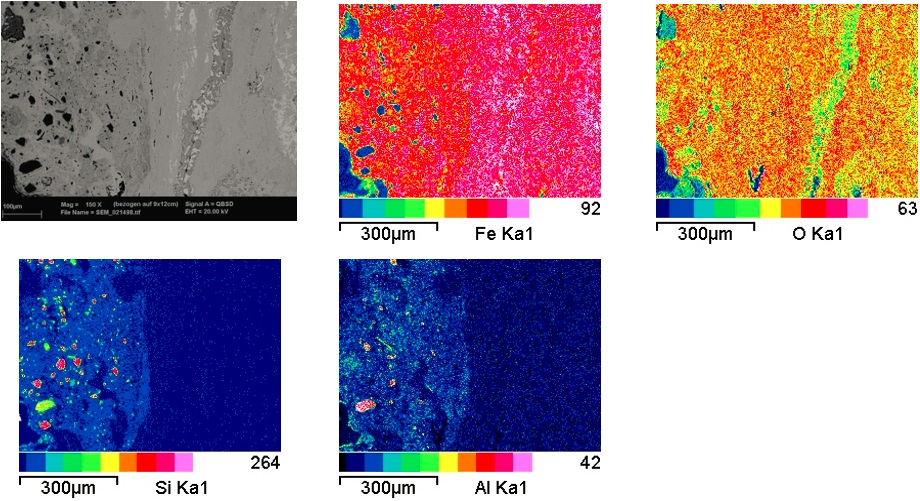
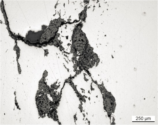
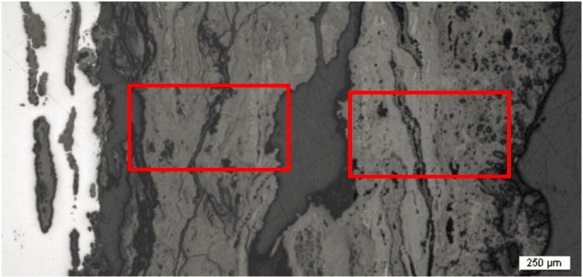
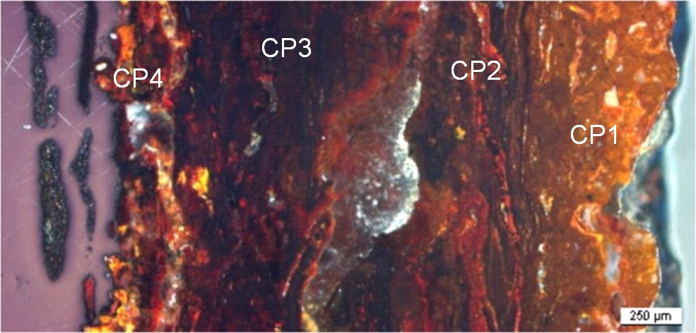
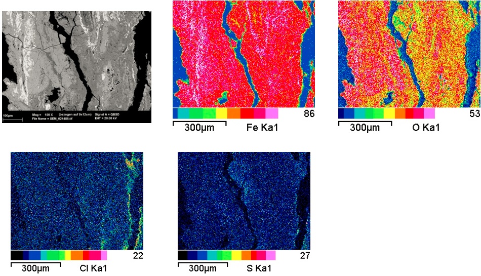
The metal - corrosion products interface is irregular (Fig. 3) and the average thickness of the corrosion crust is about 0.6mm. However, on the left side of the sample taken from the head of the chisel (Fig. 3) the corrosion crust is deeper with an average thickness of about 2mm. This area is further detailed below (Figs. 11 and 12). The corrosion crust can be divided into several layers (CP1-CP4). In bright field, and in the BSE-mode of the SEM image, darker and lighter regions are visible (Figs. 11, 13 and 14). In this area the corrosion layer contains typical trace elements of the metal (As and P, Table 3). In polarised light we see a dark-red zone in which different grey zones are included (Fig. 12). The element mapping and the analyses show that at the metal - corrosion crust interface iron chlorides occur (Figs. 13 and Table 3, CP4 in Fig. 4). Only the outer zone, which has reacted with the soil, has a different colour (orange) and incorporates many rock inclusions (Si, Al and Ca) (Fig. 14 and Table 3, CP1 in Fig. 4).
|
Elements |
O | Al | Si | P | S | Cl | Ca | Fe | As | Total |
|---|---|---|---|---|---|---|---|---|---|---|
| Rim outside, orange, CP1, Fig. 12 | 28 | 2.3 | 6.0 | < | < | < | 0.6 | 65 | < | 103 |
|
Orange zone, outside with little rock inclusions, CP1, Fig. 12 |
29 | 2.5 | 7.1 | < | < | < | < | 65 | < | 105 |
| Light-grey, outside, CP2, Fig. 14 |
22 | < | 0.7 | < | < | < | < | 75 | < | 98 |
| Mixed zone, middle, CP3, Fig. 14 |
22 | < | < | < | < | < | < | 73 | < | 96 |
| Dark-grey, inside, CP4, Fig. 13 | 24 | < | < | < | 1.9 | 2.0 | < | 74 | < | 102 |
| Light-grey, inside, CM, Fig. 13 |
22 | < | < | < | < | < | < | 73 | 0.6 | 97 |
| White, inside, M, Fig. 13 | 25 | < | < | < | < | < | < | 84 | 0.6 | 111 |
Table 3: Chemical composition (mass %) of the corrosion layers (from Figs. 12 to 14). Method of analysis: SEM/EDS, Laboratory of Analytical Chemistry, Empa.
 Credit HE-Arc CR.
 Credit HE-Arc CR
Fig. 12: Micrograph (same as Fig. 11) corresponding to the stratigraphy of Fig. 4, unetched, polarised light. From left to right: the metal in violet, the successive corrosion layers having a yellow (CP4), grey (CP3) to dark-red colour (CP2). The outer layer is orange-brown with quartz inclusions in white (CP1),
 Credit HE-Arc CR.
Uniform - transgranular
?
Nothing to report.
Corrected stratigraphic representation: none.
The chisel is forged from a medium-hard iron alloy. The hardened tip is missing. Both forging techniques used to produce the tool (butt-welding and edge-to-edge welding) are very sophisticated. The chemical composition of the metal is consistent with the iron worked in the smithies of the village Develier-Courtételle JU. The chemical composition of the slag inclusions does not indicate that the item was made of locally smelted bean ore. It seems that bones or bone ash were used when forging the chisel. The metal is severely attacked by corrosion. At the metal - corrosion crust interface an active corrosion front including chlorides is present. This is not surprising as no stabilisation treatment has been carried out. The part of the corrosion layer which has been examined seems to be complete. The limit of the original surface can be located by the presence of external markers such as sand grains and rock fragments (Si, Al) incorporated in the outer corrosion layers.
|
References on object and sample |
|
References object References sample |
|
References on analytic methods and interpretation |
| 3. Lang, J. (1984) The technology of Celtic Iron Swords. In: The crafts of the blacksmith (ed. Scott, B.G. and Cleere, H.) Belfast, 61-72. |