Situla EMT09-554.665
Christian. Degrigny (HE-Arc CR, Neuchâtel, Neuchâtel, Switzerland) & Marie-Jeanne. Scholl (HE-Arc CR, Neuchâtel, Neuchâtel, Switzerland) & Valentin. Boissonnas (HE-Arc CR, Neuchâtel, Neuchâtel, Switzerland)
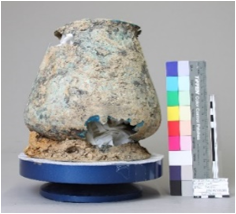
Situla (Fig. 1). Attached to two riveted iron loops is an iron handle terminating in two swan heads (not shown here). Dimensions of the main body: Hmax = 340mm, Ømax = 220mm.
Situla
Mormont sanctuary, La Sarraz, Vaud, Switzerland
Excavated in 2011
Iron Age
La Tène D
Soil
Musée cantonal d’archéologie et d’histoire, Lausanne, Vaud
Musée cantonal d’archéologie et d’histoire, Lausanne, Vaud
EMT09/554.665
Not conserved
The size and quality of the object makes it likely that is was reserved for important occasions or for ritual use. Secondary use could be a votive offering. Burial condition: inside a 3 meters deep hole in upside-down position.
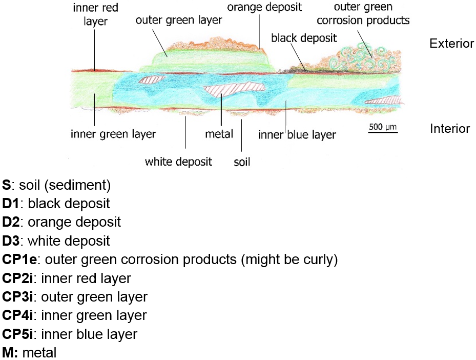
The schematic representation below gives an overview of the corrosion layers encountered on the situla from a first visual macroscopic observation (additional e and i within the coding correspond to strata in contact with the environment (e) and internal strata (i)).
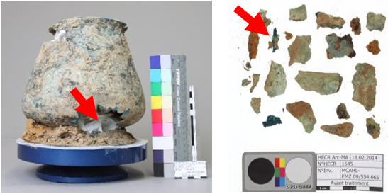
The sample was cut from a detached fragment of the upper part of the main body of the situla in Fig. 2. The cross-section is representative of the entire thickness (0.5 mm) of the object’s body where on the outside there is a thicker accumulation of corrosion including curly malachite clusters (Fig. 3). A metallic core is still present inside the corrosion products layers (Fig. 4).
Tin Bronze
Cold worked (hammering on a counter-mould), annealed but no final annealing
None
HE-Arc CR, Neuchâtel, Neuchâtel
Musée cantonal d’archéologie et d’histoire, Lausanne, Vaud
2014, metallography and chemical analyses (FTIR, SEM-EDS)
Nothing to report.
Analyses performed:
Metallography (etched with ferric chloride reagent), SEM-EDS, FTIR, Raman spectroscopy and XRD.
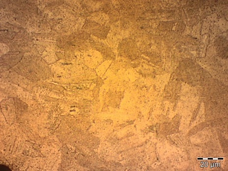
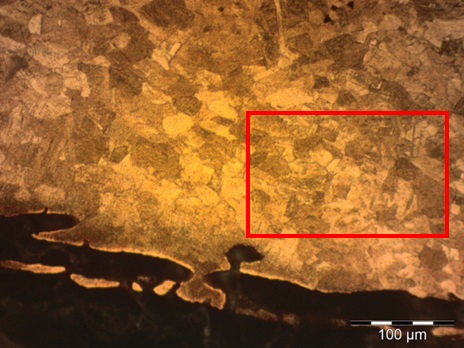
The remaining metal is a dense tin bronze (Fig. 7, Table 1), showing no inclusion. In bright field, the etched alloy shows a structure principally consisting of polygonal alpha phase grains (Fig. 8). Some of the grains include twin lines (Fig. 9). The presence of strain lines (slip lines) indicates a final cold work without annealing (Fig. 9).
| Elements | Cu | Sn |
|---|---|---|
| mass% | 90 | 10 |
Table 1: Chemical composition of the metal. Method of analysis: SEM-EDS, Lab of Electronic Microscopy and Microanalysis, IMA (Néode), HEI Arc.
 Credit HEI Arc, S.Ramseyer.
 Credit HE-Arc CR.
Polygonal grain with twin and strain lines
Cu
Sn
Nothing to report.
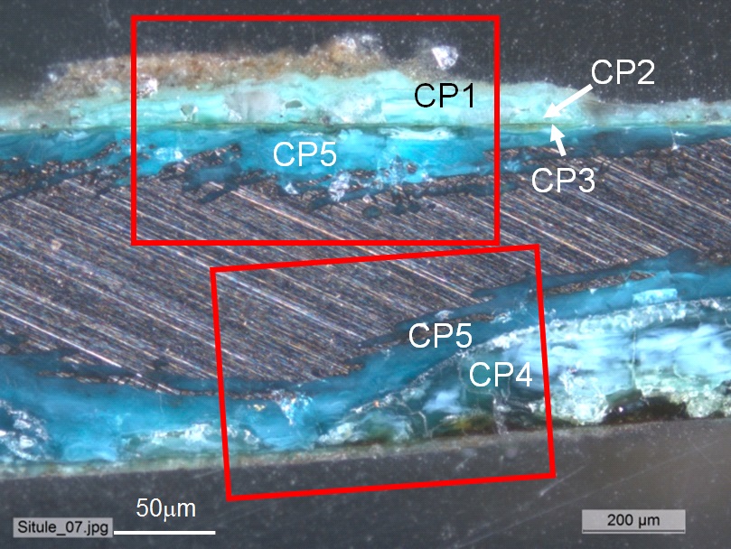
The corrosion crust is heterogeneous and has in places completely replaced the metal. The metal – corrosion products interface is irregular due to transgranular corrosion (Figs 7-8). In most cases, the corrosion crust can be divided in three main layers: an inner compact blue layer directly on the metal core (CP5, Figs. 6, 10 and 11 and CP3, Fig. 5). In areas of extensive corrosion this blue layer coexists with a friable green layer (CP4, Figs. 6, 10 and 11 and CP2, Fig. 5). Depending on the area either a very fine dark green (CP3, Fig. 6 and Fig. 10) or red corrosion layer (CP2, Fig. 6 and Fig. 10) marks the limit of the original surface. It is followed by an external fourth layer, consisting of friable and sometimes curly pale green corrosion products intermingled with soil products (CP1, Fig. 6 and Fig. 10 and 13). In heavily worked and fragile parts of the object a cleavage between the inner layers of blue and green corrosion is present, rendering the green corrosion vulnerable to loss (Fig. 11).
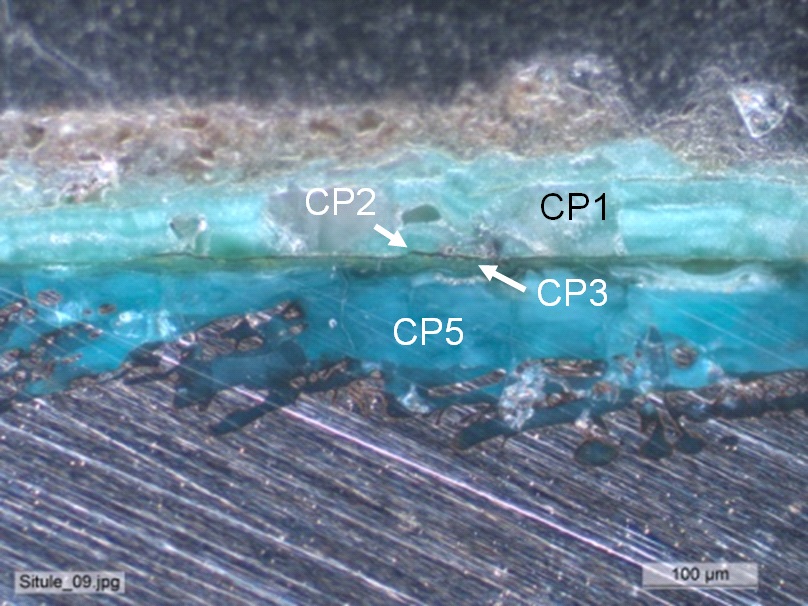
There are 2 stratigraphies (Fig. 5 corresponding to the interior face of the situla and Fig. 6 to its exterior face). The strata are similar in composition but their coding is different: CP1 to CP3 in Fig. 5 correspond to CP3 to CP5 in Fig. 6. Since the stratigraphy of Fig. 6 is more complete, the composition of each of its strata is given below.
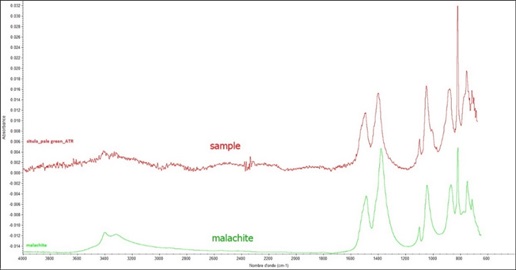
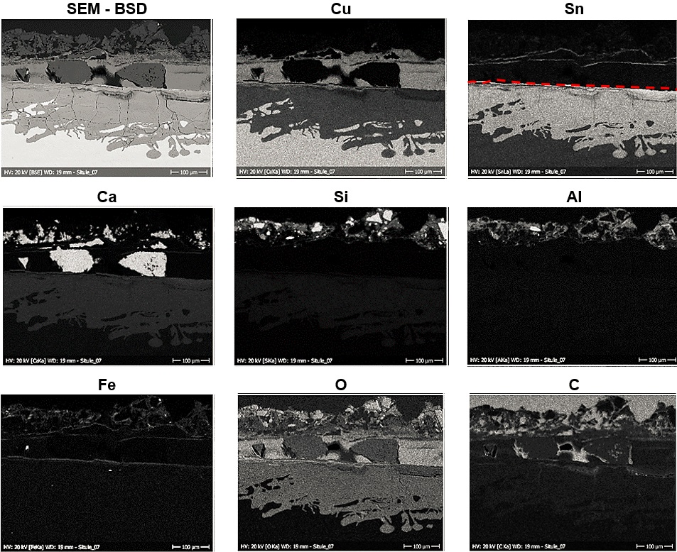
The inner layers (CP3-CP5) are Sn and O-rich and depleted in Cu (Table 2). The outer layers (CP1 and CP2) are Cu and O-rich, contain no Sn, and are contaminated with Ca, Si, Al and Fe coming from the soil (Fig. 12). The colour of the corrosion crust varies according to the content of Sn (the more Sn, the darker green or blue the corrosion). FTIR on the inner blue (CP5 and Fig. 14) and outer green (CP1 and Fig. 15) layers were difficult to interpret. Only malachite could be identified in both cases. XRD spectra could not be interpreted because of the deficiency of peaks.
The limit of the original surface is well defined (interface of CP1 and CP2) but due to the fragility of the inner corrosion layers it was difficult to uncover.
|
Elements |
O | Cu | Sn |
|---|---|---|---|
| Outer green layer (CP1) | +++ | +++ | nd |
| Inner green layer (CP4) | ++ | + | +++ |
| Inner blue layer (CP5) | ++ | + | +++ |
| Remnant metal phase | nd | +++ | + |
Table 2: Chemical composition of the corrosion crust from Fig. 10. SEM-EDS, Lab of Electronic Microscopy and Microanalysis, IMA (Néode) (+++: high concentration, ++ medium concentration, + low concentration, nd: not-detected).
 Credit HE-Arc CR.
 Credit HEI Arc, S.Ramseyer.
 Credit HEI Arc, S.Ramseyer.
 Credit HE-Arc CR.
 Credit HE-Arc CR.
Multiform - transgranular
Type I (Robbiola)
Nothing to report.
The schematic representation of corrosion layers of Fig. 3 integrating additional information (e and i within the coding correspond to strata in contact with the environment (e) and internal strata (i)) based on the analyses carried out is given in Fig. 16.
The metal structure of this low-tin bronze shows extensive cold work and multiple annealing cycles with a final cold work. The total absence of inclusions highlights a highly developed knowledge in bronze metallurgy. The metal is much corroded. Transgranular corrosion is visible. The majority of the internal corrosion products are composed of copper carbonates that have replaced much of the metal. Curly malachite has developed in clusters on the outside of the surface. This pattern is characteristic of a long-term burial period. The presence of inner enriched Sn layers shows a decuprification phenomenon (dissolution of Cu). Because of the friable nature of the inner green layer that supports the limit of the original surface, as well as its cleavage with the blue layer underneath, the original surface has become very fragile. The corrosion is thought to be of type 1 according to Robbiola et al. 1998.
|
References on object and sample |
|
Reference object Reference sample |
|
References on analytic methods and interpretation |
| 4. Robbiola, L., Blengino, J-M., Fiaud, C. (1998) Morphology and mechanisms of formation of natural patinas on archaeological Cu-Sn alloys, Corrosion Science, 40, 12, 2083-2111. |